POWER DISTRIBUTION
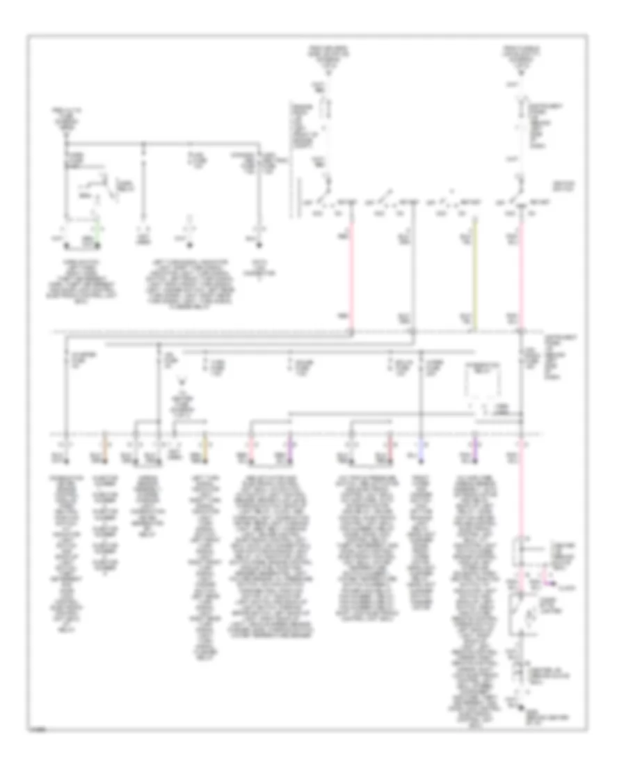
Power Distribution Wiring Diagram (1 of 3) for Toyota Avalon XLS 1996

List of elements for Power Distribution Wiring Diagram (1 of 3) for Toyota Avalon XLS 1996:
- (1995) (1996)
- (1996) (1995)
- (can- ada) left head hi 15a
- (can- ada) right head hi 15a
- (canada) head fog relay
- (canada) left head lo fuse 10a
- (canada) right head lo fuse 10a
- (left fender apron, engine harness) e6
- (rear of engine, on intake manifold, engine harness) e10
- (usa) left head 15a
- (usa) right head 15a
- A/c amplifier, a/c power transistor, blower motor, blower resistor, low speed blower resistor, extra high speed relay, heater control switch, heater relay
- A/c amplifier, cruise control elec- tronic control unit (ecu)
- A/c condenser fan motor, radiator fan motor, fan number relay, fan number relay
- Abs actuator, abs electronic control unit (ecu)
- Abs fuse 60a
- Alt fuse 120a
- Alt-s fuse 5a
- Am1 fuse 80a
- Am2 fuse 30a
- Auto antenna motor and relay, radio and player, stereo component amplifier
- Automatic light control sensor, clock, combin- ation meter, open door warning light, main day time running light relay, left front door courtesy light, right front door courtesy light, left front door courtesy switch, right front door courtesy switch, left rear door courtesy switch, right rear door courtesy switch, left door key lock and unlock switch, front personal light, ignition key cylinder light, interior light, luggage compartment light, luggage compartment light switch, moon roof control switch, interior light noise filter, left rear personal light, right rear personal light, theft deterrent and door lock control electronic control unit (ecu), left vanity light, right vanity light, wireless door lock control electronic control unit (ecu), integration relay
- Battery
- Cds fuse 30a
- Circuit opening relay, data link connector 1, electronically controlled transmission solenoid, engine control module, heated oxygen sensor (bank1 sensor1), heated oxygen sensor (bank2 sensor1), heated oxygen sensor (bank1 sensor2), idle air control valve, mass air flow meter, egr vacuum solenoid valve (vsv), evap vacuum solenoid valve (vsv), fuel pressure- up vacuum solenoid valve (vsv), intake air control vacuum solenoid valve (vsv), vapor pressure sensor vacuum soleniod valve (vsv), fuel pump and sender
- Coil
- Dome fuse 7.5a
- Driver's side j/b (behind left kick panel)
- Drl fuse 5a
- Drl number 2 relay (canada)
- Drl number 3 relay, drl number 4 relay
- E6 (engine harness, left fender apron)
- Ecu-b fuse 5a
- Efi fuse 15a
- Efi relay
- Eng main relay
- Engine room j/b (on left front of engine compt)
- Fan number relay
- Fusible link block f11 (center of left front fender)
- Fusible link block f9 (left front of engine compt, near engine room j/b)
- Generator
- Harness, behind left headlight)
- Head relay (usa)
- Htr fuse 50a
- Ig sw fuse 40a
- Left low beam headlight
- Main fuse 40a
- Nca
- Rad number fuse 15a
- Radiator fan motor, fan number 1 relay
- Rdi fuse 30a
- Red
- Right low beam headlight
- Short pin
- St relay
- Starter
- Sub r/b (canada) (on left front of engine compt)
- To horn fuse (diagram 2 of 3)
- To instrument panel j/b (pin 1a) (diagram 2 of 3)
- To instrument panel j/b (pin 2a) (diagram 3 of 3)
- To instrument panel j/b (pin 3a) (diagram 2 of 3)
- Usa only
- Usa: combination meter; high beam indicator light; combin- ation switch; right high beam headlight; right low beam headlight; canada: combination meter; high beam indicator light; right high beam headlight; drl number 3 relay; drl number 4 relay
- Usa: combination switch; left high beam headlight; left low beam head- light; canada: high beam indicator light; left high beam headlight; right high beam head- light; drl number 3 relay; drl number 4 relay
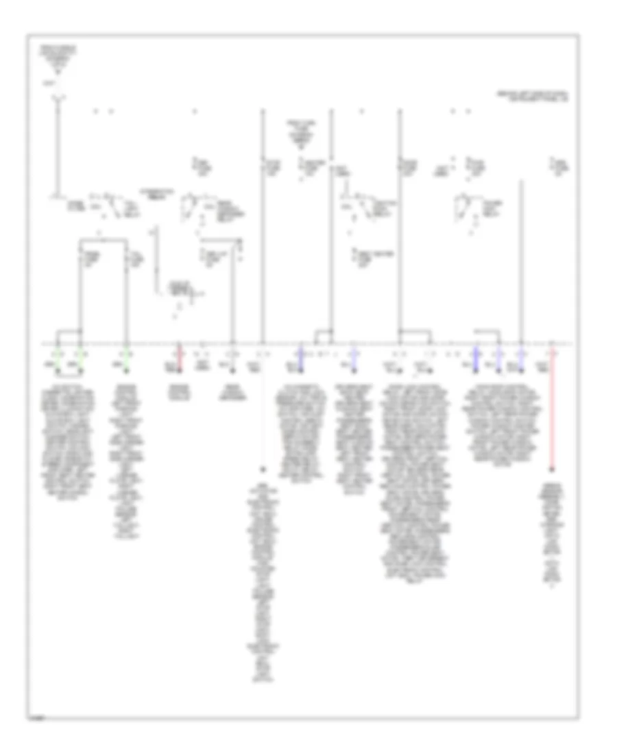
Power Distribution Wiring Diagram (2 of 3) for Toyota Avalon XLS 1996
List of elements for Power Distribution Wiring Diagram (2 of 3) for Toyota Avalon XLS 1996:
- (1995)
- (1996)
- (canada) obd fuse 7.5a
- (not used)
- (usa) obd trac fuse 7.5a
- A/c amplifier, airbag sensor assembly, auto antenna motor and relay, back-up light relay, comb- ination meter, cruise control electronic control unit (ecu), a/t indicator light switch diode, engine control module, key interlock solenoid, park/ neutral position switch; a/t indicator light switch and back-up light switch, radio and player, remote control mirror switch, left back-up light, right back-up light, left remote control mirror, right remote control mirror, shift lock electronic control unit (ecu), stereo component amplifier, theft deterrent and door lock control electronic control unit (ecu)
- A/c triple pressure switch, abs actuator and electronic control unit (ecu), a/c amplifier, auto antenna motor and relay, cruise control electronic control unit (ecu), fan number 3 relay diode, door lock control relay, theft deterrent and door lock control electronic control unit (ecu), water temperature switch number 1, water temperature switch number 2, power main relay, fan number 1 relay, fan number 2 relay, fan number 3 relay, shift lock electronic control unit (ecu)
- Abs actuator and electronic control unit (ecu), a/c switch, automatic light control sensor, brake fluid level warning switch, back-up light relay, clock, abs warning light, combination meter, rear light warning light, seat belt warning light, cruise control electronic control unit (ecu), data link connector 2, main daytime running light relay, a/t indicator light switch diode, engine control module, fuel pump and sender, generator, light failure sensor, oil pressure switch, o/d main switch, park/neutral position switch; a/t indicator light switch and back-up light switch, parking brake switch, left back-up light, right back-up light, vehicle speed sensor, washer level warning switch, water temperature sender
- Acc
- Airbag sensor assembly, charge warning light, combination meter, generator, efi relay
- C c
- Center j/b (behind glove box)
- Cig/ radio fuse 15a
- Cigar- ette lighter
- Clock
- Coil
- Combination meter, engine control module, park/ neutral position switch; a/t indicator light switch and back-up light switch, theft deterrent and door lock control electronic control unit (ecu), st relay
- Data link connector
- Ecu-ig fuse 10a
- Engine room j/b (on left front of engine compt)
- From alt-s fuse (diagram 1 of 3)
- From driver's side j/b (pin 4d) (diagram 1 of 3)
- From fusible link block f11 (diagram 1 of 3)
- Front wiper and washer switch, main daytime running light relay, headlight cleaner diode, front wiper motor, headlight cleaner relay, headlight cleaner switch, washer motor
- G206 (behind center of i/p)
- Gauge fuse 7.5a
- Haz fuse 10a
- Horn fuse 10a
- Horn relay
- Horn switch, left horn, right horn, theft deterrent horn, theft deterrent and door lock control electronic control unit (ecu)
- Ign fuse 5a
- Ignition switch
- Injector number
- Injector number 2, injector number 3, injector number 4, injector number 5, injector number
- Instrument panel j/b (behind left side of dash)
- Integration relay
- Left turn signal indicator light, right turn signal indicator light, turn signal switch, left front turn signal light, right front turn signal light, hazard switch, left rear turn signal light, right rear turn signal light, turn signal flasher relay
- Off
- Red
- Start
- Starter fuse 5a
- To heater fuse (diagram 3 of 3)
- Turn fuse 7.5a
- Wiper fuse 20a
Power Distribution Wiring Diagram (3 of 3) for Toyota Avalon XLS 1996
List of elements for Power Distribution Wiring Diagram (3 of 3) for Toyota Avalon XLS 1996:
- (behind left side of dash) instrument panel j/b
- (not used)
- A/c magnetic clutch and lock sensor, a/c triple pressure switch, a/c amplifier, a/c switch, air inlet control servo motor, air vent mode control servo motor, fan number 3 relay diode, extra high speed relay, heater relay, mg ctl relay, heater control switch
- A/c switch, cigarette lighter, clock, combination meter, combination meter illumination, glove box light, glove box light switch, hazard switch, headlight cleaner switch, heater control switch, o/d main switch, radio and player, rheostat, stereo component amplifier, left front seat heater control switch, right front seat heater conrol switch
- Abs actuator and electronic control unit (ecu), cruise control electronic control unit (ecu), engine control module, high mounted stop light, light failure sensor, left stop light, right stop light, shift lock electronic control unit (ecu), stop light switch
- Airbag sensor assembly, comb- ination meter, srs warning light, data link conn- ector 1, data link conn- ector
- Coil
- Def fuse 40a
- Def i/up fuse 5a
- Door fuse 30a
- Door lock control relay, left front door lock motor and door unlock detection switch, right front door lock motor and door unlock detection switch, left rear door lock motor, right rear door lock motor, driver's power seat control switch, passenger's power seat control switch, driver's front vertical control power seat motor, driver's rear vertical control power seat motor, driver's reclining control power seat motor, driver's slide control power seat motor, passenger's front vertical control power seat motor, passenger's rear vertical control power seat motor, passenger's reclining control power seat motor, passenger's slide control power seat motor, theft deterrent and door lock control electronic control unit (ecu), power main relay
- Driver's seat back seat heater, driver's seat cushion seat heater, passenger's seat back seat heater, passenger's seat cushion seat heater, left front seat heater control switch, right front seat heater control switch
- Engine control module
- Engine control module, left front parking light, right front parking light, left front side marker light, right front side marker light, left license plate light, right license plate light, light failure sensor, left taillight, right taillight
- From fusible link block f11 (diagram 1 of 3)
- From turn fuse (diagram (2 of 3)
- Heater fuse 10a
- Idle up diode
- Ignition main relay
- Integration relay
- Moon roof control relay, moon roof motor, right front power window control switch, right rear power window control switch, left rear power window control switch, power window master switch, left front power window motor, right front power window motor, left rear power window motor, right rear power window motor
- Noise filter
- Panel fuse 5a
- Power main relay
- Pwr fuse 30a
- Rear window defogger
- Rear window defogger relay
- Seat heater fuse 20a
- Srs fuse 5a
- Stop fuse 15a
- Tail fuse 15a
- Tail- light relay