POWER DISTRIBUTION
Power Distribution Wiring Diagram (1 of 2) for Toyota Camry CE 1997

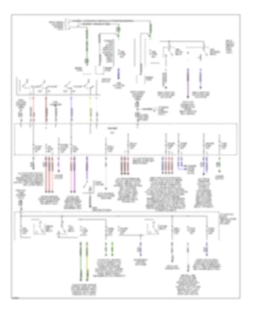
List of elements for Power Distribution Wiring Diagram (1 of 2) for Toyota Camry CE 1997:
- (canada)
- (usa)
- A/c amplifier, a/c switch, air vent mode control servo motor, engine control module, heater switch
- A/c condensor fan motor, radiator fan motor, fan 2 relay, fan 3 relay
- A/c fuse 10a
- Air bag sensor, air bag ecu, combination meter, cruise control ecu, data link connector 1
- Alt fuse 100a
- Alt-s fuse 5a
- Am2 fuse 30a
- Auto antenna motor & relay, radio and player, radio power amplifier
- Battery
- C from radio 1 fuse (diagram 1 of 2)
- Cds fuse 30a
- Combination meter, clock, door courtesy switches, drl diodes drl main relay, idle up diode, ignition key light, interior light, trunk light, moon roof control switch, park brake switch, vanity lights, wireless door lock ecu, integration relay
- Combination meter, hazard switch, front directional lights, rear directional lights, turn signal flasher
- Combination switch, drl 1 diode, integration relay, drl 4 relay (coil)
- Data link connector 1, air/fuel ratio sensor, ecm, fuel pump & sender, heated oxygen sensors, idle air control valve, ignition coil/ignitor units, mass air flow sensor, ignition noise filter, vsv's, efi relay, circuit opening relay
- Dimmer relay
- Dome fuse 7.5a
- Drl no 2 fuse 10a
- E3 (engine harness, left front fender)
- Ecu-b fuse 10a
- Efi fuse 15a
- Engine main relay
- Fusible link block (inside junction block 2, (left front fender apron)
- Generator
- Hazard fuse 10a
- Head- light relay
- Heater relay
- Horn fuse 10a
- Horn relay
- Horn switch, hi horn, lo horn, theft horn, theft deterrent ecu
- Htr fuse 50a
- J12
- Junction block 2 (left front fender apron)
- K11
- Left head fuse 10a
- Left head upper fuse 10a
- Left head- light
- Left high beam head- light
- Left low beam head- light
- Left lower head fuse 10a
- Main fuse 40a
- Radiator fan motor, fan 1 relay
- Radio 1 fuse 20a
- Rdi fuse 30a
- Red
- Relay block 1 (inside junction block 2, (left front fender apron)
- Relay block 2 (behind left headlight)
- Right head fuse 10a
- Right head upper fuse 10a
- Right head- light
- Right high beam head- light
- Right low beam head- light
- Right lower head fuse 10a
- Short pin
- Start relay
- To am1 fuse (diagram 2 of 2)
- To generator or abs fuse (diagram 2 of 2)
- To hazard fuse (diagram 1 of 2)
- To ignition switch (diagram 2 of 2)
Power Distribution Wiring Diagram (2 of 2) for Toyota Camry CE 1997
List of elements for Power Distribution Wiring Diagram (2 of 2) for Toyota Camry CE 1997:
- (japan built abs & all w/ traction control)
- (usa built abs)
- (w/o abs)
- 40a
- A/c switch, ashtray illum, blower switch, clock, lighter illum, combination meter, glove box light, hazard switch, o/d main switch, radio, rear window defogger switch, rheostat
- A/c triple pressure switch, a/c magnetic clutch & lock sensor, a/c amplifier, air vent mode servo motor, ecm, a/c diode, rear window defog switch& relay, htr relay
- A/c triple pressure switch, abs actuator & ecu, abs ecu, auto antenna, cruise control ecu, a/c diode, ecm, shift lock ecu, water temp switches, theft deterrent ecu, engine main relay, fan relays
- Abs & trac actuator & ecu, back-up light switch, brake fluid level switch, comb- ination meter, combination switch, cruise control ecu & clutch switch, data link conn 1 & 2, drl main relay, door lock motor & door unlock detect switches, ecm, fuel pump & sender, generator, light failure sensor, oil pressure switch, o/d switch, p/n position switch, water temp sender, washer level switch, vss, abs solenoid relay, power relay, integration relay
- Abs & traction actuator, abs actuator
- Abs actuator & ecu
- Abs ecu, abs actuator, abs & traction ecu, cruise control ecu, engine control module, light failure sensor, shift lock ecu, stop lights, stop light switch
- Abs fuse 60a
- Abs motor relay
- Abs solenoid relay
- Acc
- Air bag sensor, combination meter, ecm, generator, efi relay (coil)
- Am1 fuse
- Auto antenna, radio & player, amplifier
- Cig fuse 15a
- Cigar lighter
- Clock, air bag sensor, remote mirror switch, shift lock ecu, theft deterrent ecu
- Clutch start switch, combination meter, engine control module, park/neutral position switch, theft deterrent ecu, start relay
- Data link connector 1, combination meter, abs & traction ecu, abs ecu
- Data link connector 3
- Def fuse 40a
- Defog- ger relay
- Door fuse 25a
- Door lock motor & door unlock detect switches, integration relay, theft deterrent ecu, power relay (coil)
- Ecu-ig fuse 15a
- From am1 fuse (diagram 2 of 2)
- From am2 fuse (diagram 1 of 2)
- From fusible link block (diagram 1 of 2)
- Fuel injectors
- Fusible link block (abs w/o traction control) (behind right head- light)
- G206 (center of dash)
- Gauge fuse 10a
- Gener- ator
- Hazard switch
- Heater fuse 10a
- I/p junction block (behind lower left side of dash)
- Idle-up diode, engine control module, light failure sensor, front parking lights, rear parking (tail) lights
- Ign fuse 5a
- Ignition switch
- J10
- Lock
- Obd ii fuse 7.5a
- Of dash)
- Panel fuse 7.5a
- Power fuse 30a
- Power outlet
- Power outlet fuse 15a
- Power relay
- Power seat control switches
- Rad 2 fuse 7.5a
- Red
- Relay block 3 (behind right head- light)
- Start
- Start fuse 5a
- Stop fuse 15a
- Tail fuse 10a
- Tail- light relay
- To defog fuse (diagram 2 of 2)
- Turn fuse 7.5a
- Washer motor, wiper motor
- Wiper fuse 20a