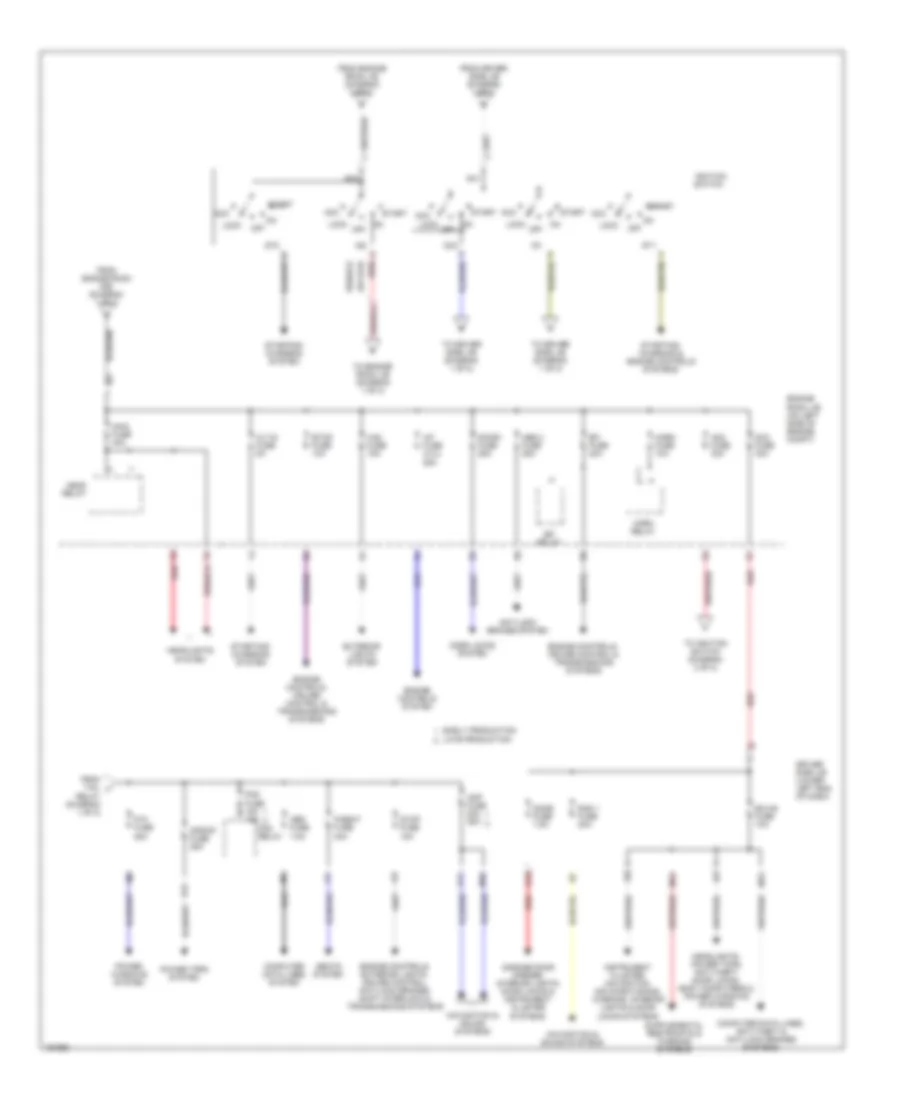
POWER DISTRIBUTION
Power Distribution Wiring Diagram (1 of 2) for Toyota Camry Solara SE 2004

List of elements for Power Distribution Wiring Diagram (1 of 2) for Toyota Camry Solara SE 2004:
- (at left "a" pillar)
- (lower left end of dash) driver side j/b
- (on left side of engine compt) engine room j/b
- (on left side of engine compt) engine room r/b
- Abs 1 fuse 50a
- Acc
- Acc relay
- Air conditioning system
- Alt fuse 120a
- Am1 fuse 7.5a
- Anti-lock brakes system
- Battery
- Body ecu
- C/opn relay
- C11
- Cds fuse 30a
- Cig fuse 15a
- Computer data lines, power windows & anti-lock brakes systems
- Cooling fans & air conditioning systems
- Cooling fans, air conditioning & defogger systems
- Cut off
- D12
- Def fuse 40a
- Def relay
- Defogger system
- Ecu acc fuse 7.5a
- Ecu-ig fuse 10a
- Engine controls & instrument cluster systems
- Engine controls system
- Exterior lights system
- F10
- F11
- F12
- F14
- F16
- Fan 1 relay
- From ig1 relay (diagram 1 of 3)
- From ignition switch (diagram 2 of 2)
- Front power outlet
- Gauge1 fuse 10a
- H16
- Headlights system
- Htr fuse 10a
- Htr fuse 50a
- Ig1 relay
- Ig2 fuse 10a
- Ign fuse 15a
- Ii (at left "a" pillar)
- Instrument cluster system
- Interior lights & instrument cluster systems
- J/c 4 (on top of engine)
- J12
- L10
- M10
- M16
- M19
- M20
- Mir htr fuse 10a
- Navigation & sound systems
- O13
- P/point fuse 15a
- Panel fuse 10a
- Pnk
- Power tops & mirrors systems
- Pwr relay
- R10
- Rad fuse 10a
- Rdi fuse 30a
- Rear power outlet
- S-htr fuse 20a
- Seats system
- Shift interlock, mirrors & instrument cluster systems
- Starting/ charging system
- Starting/charging, engine controls, exterior lights, warning, cruise control, anti-lock brakes, transmissions, shift interlock, instrument cluster & navigation systems
- Tail fuse 10a
- Tail relay
- To acc relay (diagram 1 of 2)
- To engine room j/b (diagram 2 of 2)
- To ignition switch (diagram 2 of 2)
- To p/w fuse (diagram 2 of 2)
- Transmissions, exterior lights, anti-lock brakes, navigation, cruise control & body computer systems
- Trly
- Wash fuse 15a
- Wip fuse 25a
- Wiper/ washer system
Power Distribution Wiring Diagram (2 of 2) for Toyota Camry Solara SE 2004
List of elements for Power Distribution Wiring Diagram (2 of 2) for Toyota Camry Solara SE 2004:
- A/f fuse (3.3l) 25a
- Abs 2 fuse 25a
- Acc
- Alt-s fuse 5a
- Am1
- Am2
- Am2 fuse 30a
- Amp fuse 20a 25a
- Anti-lock brakes system
- Computer data lines system
- Computer data lines, anti-theft & anti-lock brakes systems
- Dcc fuse 30a
- Dome fuse 7.5a
- Door locks system
- Door1 fuse 25a
- Driver side j/b (lower left end of dash)
- Early production
- Ecu-b fuse 10a
- Efi fuse 20a
- Efi relay
- Engine controls system
- Engine controls, cruise control & transmissions systems
- Engine controls, exterior lights, cruise control, anti-lock brakes, shift interlock & transmissions systems
- Engine room j/b (on left side of engine compt)
- Etcs fuse 10a
- Exterior lights system
- Fog fuse 15a 10a
- Fog relay
- From driver side j/b (diagram 1 of 2)
- From engine room j/b (diagram 2 of 2)
- From engine room r/b (diagram 1 of 2)
- From tail j
- G12
- Garage door opener, interior lights, door locks & instrument cluster systems
- Haz fuse 15a
- Head relay
- Headlights system
- Headlights, power tops, anti-theft, door locks, body computers & power windows systems
- Horn fuse 10a
- Horn relay
- Ig1
- Ig2
- Ignition switch
- Instrument cluster, navigation, air conditioning, warning, interior lights & door locks systems
- K11
- Late production
- Lock
- M13
- M14
- M18
- Main fuse 40a
- Navigation & sound systems
- Obd fuse 7.5a
- Off
- P/seat fuse 30a
- P/w fuse 25a
- Power tops system
- Power windows system
- R12
- Rad 1 fuse 20a
- Red
- Red)
- Relay (diagram 1 of 2)
- S/roof fuse 25a
- Seats system
- St1
- St2
- Start
- Starting/ charging & engine controls systems
- Starting/ charging system
- Stop fuse 15a
- To driver side j/b (diagram 1 of 2)
- To engine room j/b (diagram 1 of 2)
- To ignition switch (diagram 2 of 2)