POWER DISTRIBUTION
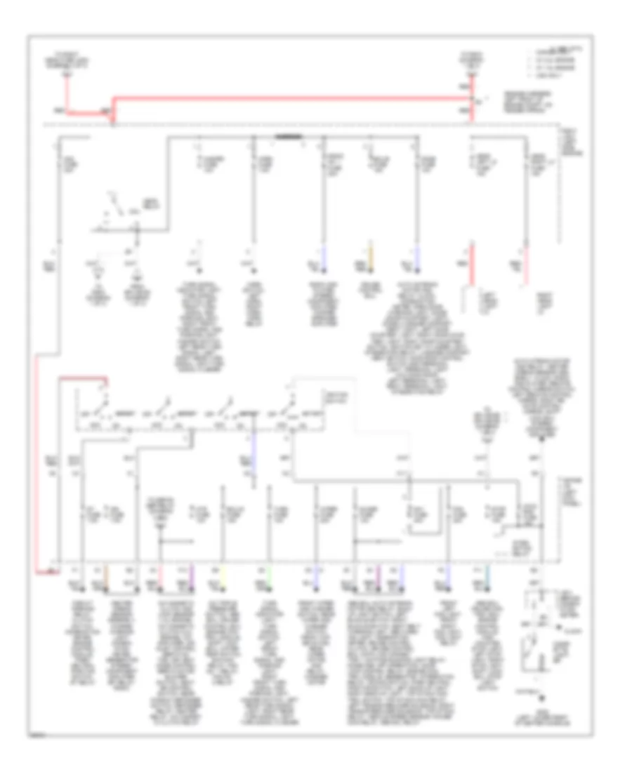
Power Distribution Wiring Diagram (1 of 3) for Toyota Celica GT 1997

List of elements for Power Distribution Wiring Diagram (1 of 3) for Toyota Celica GT 1997:
- (engine harness, left end of engine compt)
- :canada only
- :w/ 1.8l engine
- :w/ 2.2l engine
- A/c condenser fan motor, radiator fan motor, remote control mirror switch, fan no. 2 relay, fan no. 3 relay
- A/c dual pressure switch
- A/c fuse 10a
- Abs actuator, abs mtr relay, abs sol relay
- Abs fuse 50a
- Alt fuse 100a
- Alt-s fuse 7.5a
- Battery
- C 1995 vftc
- Cds fuse 30a
- Circuit opening relay, data link connector 1, engine control module, oxygen sensor, heated oygen sensor, idle air con- trol valve, vsv, efi relay, fuel sender
- Coil
- Combination meter, data link connector 1
- Data link con- nector 3
- Drl fuse 7.5a
- Drl no. 2 relay
- Drl no. 3 relay, drl no. 4 relay
- E/g main relay
- E3 (engine harness, left front of engine compt, on fender apron)
- E5 e8 (engine harness, left end of engine compt)
- Efi fuse 15a
- From inpane j/b (diagram 2 of 3)
- From r/b 2/ j/b 2 (diagram 2 of 3)
- From splice e3 (diagram 2 of 3)
- Gener- ator
- Generator
- Head hi left fuse 15a
- Head hi right fuse 15a
- Heater control switch
- Heater relay
- High beam indi- cator light, headlight hi left, fog light re- lay, drl no. 4 relay
- High beam indicator light, drl no. 3 relay, drl no 4 relay, headlight hi right
- Htr fuse 40a
- I15 (i/p harness, upper right end of dash)
- J/c 5 (behind left side of i/p)
- Main fuse 60a
- Nca
- Obd ii fuse 7.5a
- Pnk
- R/b 2/ j/b 2 (left side of engine)
- R/b 4 (right kick panel)
- R/b 6 (left front of engine compt)
- Radiator fan motor, fan no. 1 relay
- Rdi fuse 30a
- Red
- Srs wrn fuse 7.5a
- St re- lay
- Starter
- To head relay (diagram 2 of 3)
- To inpane j/b (diagram 3 of 3)
Power Distribution Wiring Diagram (2 of 3) for Toyota Celica GT 1997
List of elements for Power Distribution Wiring Diagram (2 of 3) for Toyota Celica GT 1997:
- (engine harness, left front of engine compt, on fender apron)
- :canada only
- :usa only
- :w/ 1.8l engine
- :w/ 2.2l engine
- A/c magnetic clutch and lock sensor (1.8l engine), a/c magnetic clutch (2.2l engine), a/c amplifier, air inlet control servo mo- tor, air vent mode control servo motor, blower switch, heat- er control switch, rear window defogger switch, defogger relay, heater relay, a/c magnet- ic clutch relay
- A/c triple pressure switch, abs ecu, cruise control ecu, engine con- trol module, shift lock ecu, water temp switch, e/g main relay, fan no. 1 relay, fan no. 2 relay
- Abs ecu, auto antenna motor and relay, back up light switch, left buckle switch, right buckle switch, seat belt warning light, abs warn- ing light, combination meter, cruise control clutch, cruise control ecu, data link connec- tor 1, daytime running light relay, diode (key off operation), door lock control relay, engine con- trol module, generator, integration relay, od main switch, park neutral position switch, left back-up light, right back-up light, top stack con- trol switch, top stack main relay, left tension reducer solenoid, right tension reducer solenoid, top stack relay, vehicle speed sensor, power main relay, abs sol relay
- Abs ecu, cruise con- trol ecu, engine control module, high mounted stop light, left stop light, right stop light, shift lock ecu, stop light switch
- Acc
- Am1 fuse 40a
- Am2 fuse 30a
- Auto antenna motor and relay, clock, combination meter, open door warning light, diode (door courtesy light), diode (luggage compart- ment light), left door courtesy light, right door cour- tesy light, right door courtesy switch, ignition key cylinder light, integration relay, luggage compart- ment switch, moon roof control switch and personal light, personal light (w/o moon roof), left personal light, right personal light, integration relay
- Auto atenna motor and relay, center airbag sensor ass- embly, clock, radio and player, remote control mirror switch, left remote control mirror, right re- mote control mirror, shift lock ecu, stereo component amplifier
- C 1995 vftc
- C11
- Center airbag sensor assembly, charge warning light, combin- ation meter, generator stereo component amplifier, efi relay, radio
- Cig & rad fuse 15a
- Cigar- ette light- er
- Circuit opening relay, clutch switch, combination meter, engine control module, park/ neutral position switch, st relay
- Clock
- Coil
- Cruise control ecu,
- Dome fuse 10a
- Ecu-b fuse 15a
- Ecu-ig fuse 15a
- F11
- F13
- Fog fuse 20a
- From splice e3 (diagram 1 of 3)
- Front left fog light, front right fog light, fog light relay
- Front wiper and washer switch, rear wiper and washer switch, front wip- er motor, rear wiper motor and relay, washer motor
- G302 (left lower front of center console)
- Guage fuse 10a
- Hazard fuse 10a
- Head left lo fuse 15a
- Head relay
- Head right lo fuse 15a
- Horn fuse 7.5a
- Horn switch, left horn, right horn, horn relay
- Htr fuse 10a
- Ign fuse 7.5a
- Ignition switch
- Inpane j/b (left kick panel)
- Integ- ration relay
- J/b 3 (behind combin- ation meter)
- Left head- light lo
- Off
- R/b 2/ j/b 2 (left side engine)
- Radio and player, stereo component amplifier, woofer speaker amplifier
- Radio no. 1 fuse 20a
- Red
- Right head- light lo
- Short pin
- St fuse 7.5a
- Start
- Stop fuse 15a
- To defog- ger relay (diagram 3 of3)
- To r/b 6 (diagram 1 of 3)
- To right head fuse (usa) (diagram 3 of 3)
- To splice e5 splice e8 (diagram 1 of 3)
- Turn fuse 10a
- Turn signal indicator light, turn signal switch, left front turn signal and parking light, right front turn signal and parking light, hazard switch, left rear turn signal light, right rear turn signal light, turn signal flasher
- Turn signal indicator light, turn signal switch, left front turn signal and parking light, right front turn signal and parking light, hazard switch, left rear turn signal light, right rear turn signal light,turn signal flasher
- Wiper fuse 20a
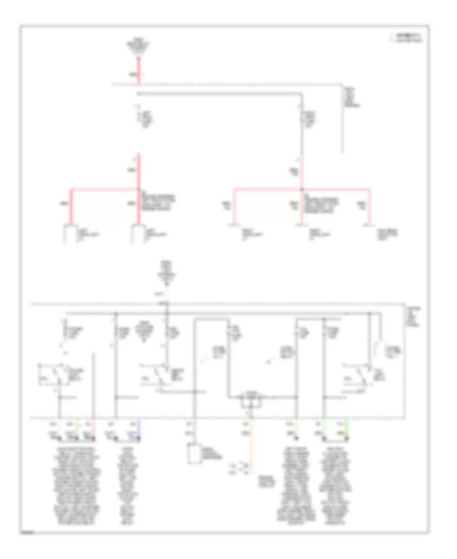
Power Distribution Wiring Diagram (3 of 3) for Toyota Celica GT 1997
List of elements for Power Distribution Wiring Diagram (3 of 3) for Toyota Celica GT 1997:
- 1.8l
- 2.2l
- :convertible
- :usa only c 1995 vftc
- Ashtray illumination, cigarette lighter, clock, combination meter, glove box light, glove box light switch, hazard switch, heater control switch, o/d main switch, radio and player, rear window defogger switch, rheostat
- Coil
- D10
- D12
- Def fuse 30a
- Defog- ger relay
- Diode
- Door fuse 30a
- Door lock control relay, top stack bypass switch, left top stack motor, right top stack motor, top stack relay, power main relay
- E3 (engine harness, left front of en- gine compt, on fender apron)
- Engine control module
- F12
- From head relay (diagram 2 of 3)
- From htr fuse (diagram 2 of 3)
- From r/b 2/ j/b 2 (diagram 1 of 3)
- G10
- High beam indicator light
- Inpane j/b (left kick panel)
- Integ- ration relay
- Left front side marker light, right front side marker light, left front turn signal and parking light, right front turn signal and parking light, license plate light, left tail- light and rear side marker, right taillight and rear side marker, diode (idle-up)
- Left head fuse 15a
- Left headlight hi
- Left headlight lo
- Mir- htr fuse 10a
- Moon roof control relay, moon roof control switch, moon roof limit switch, moon roof motor, power window control switch, power window master switch, left power window motor, right power window dow motor, left quar- ter power window switch, right quar- ter power window switch, left quarter power window motor, right quarter pow- er window motor, power main relay
- Noise filter no. 1
- Noise filter no. 2
- Panel fuse 7.5a
- Power fuse 30a
- Power main relay
- R/b 2/ j/b 2 (left side engine)
- Rear window defogger
- Red
- Right head fuse 15a
- Right headlight hi
- Right headlight lo
- Tail fuse 15a
- Tail- light relay