POWER DISTRIBUTION
Power Distribution Wiring Diagram (1 of 2) for Toyota Celica GT 2003

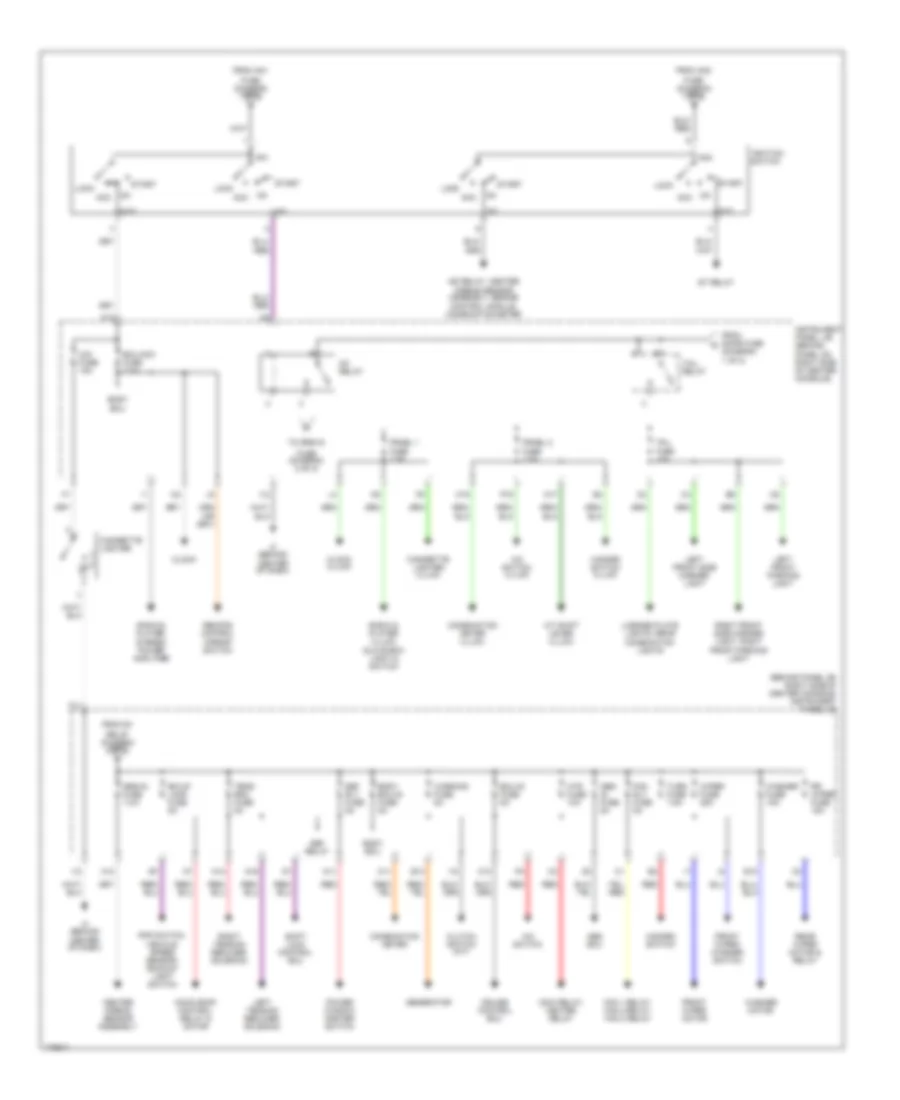
List of elements for Power Distribution Wiring Diagram (1 of 2) for Toyota Celica GT 2003:
- (1.8l gt-s)
- (behind panel on right side of center console)
- (left side of engine compt) engine room j/b
- Abs 1 fuse 40a
- Abs 2 fuse 25a
- Abs mtr relay
- Abs sol relay
- Alt fuse 120a
- Alt-s fuse 7.5a
- Am1 fuse 25a
- Am2 fuse 7.5a
- Auto ant fuse 15a
- Auto antenna control relay
- Battery
- Body ecu
- C/opn relay
- Cds fuse 30a
- Clock
- Combination meter
- D10
- D11
- Data link connector
- Dcc fuse 25a
- Def fuse 30a
- Def relay
- Dome fuse 7.5a
- Door control receiver
- Door fuse 20a
- Drl 1 head lvl fuse 7.5a
- Drl 2 dimmer relay
- Drl 3 relay
- Drl relay 2 (w/hid)
- Drl relay 3 (w/o hid)
- Drl relay 4 (w/o hid)
- Ecu-b fuse 7.5a
- Efi 1 fuse 10a
- Efi 2 fuse 10a
- Efi fuse 20a
- Efi relay
- Engine control module
- Engine control module (1.8l gt-s)
- Engine control module, mass air flow meter, idle air control valve
- Engine room j/b (left side of engine compt)
- Engine room j/b 1 (left side of engine compt)
- Engine room r/b 1 (left side of engine compt)
- Engine room r/b 2 (left side of eng compt)
- Engine room r/b 2 (left side of engine compt)
- Etcs fuse 10a
- F16
- F20
- F29
- Fan 1 relay
- Fan 3 relay
- Fl p/w fuse 20a
- Fr fog fuse 15a
- Fr p/w fuse 20a
- Front fog light relay
- Generator
- Haz fuse 10a
- Hazard switch
- Head relay
- Heated oxygen sensors, vsv valves
- Heater relay
- Horn fuse 10a
- Horn relay
- Htr fuse 50a
- Ig2 fuse 15a
- Ig2 relay
- Ignition coils & igniters, injectors, noise filter
- Instrument panel j/b to tail relay (diagram 2 of 2)
- K11
- Left headlight cntrl ecu (w/hid)
- Left high beam headlight
- Left low beam headlight (w/o hid)
- Lh lwr head fuse 15a
- Lh upr head fuse 10a
- Luggage compartment light
- M17
- Main fuse 40a
- Main fuse link 12 ga
- Moon roof control relay & motor
- Mpx-b fuse 7.5a
- N13
- Nca
- Obd fuse 7.5a
- Personal light
- Pnk
- Power window master switch
- Radio & player, stereo power amplifier
- Radio fuse 15a
- Rdi fuse 30a
- Red
- Rh lwr head fuse 15a
- Rh upr head fuse 10a
- Rh upr head fuse 20a
- Right low beam headlight, front fog light relay, combination meter
- S/roof fuse 15a
- St fuse 7.5a
- St relay
- Starter
- Stop fuse 10a
- Stop light switch
- Switch (diagram 2 of 2)
- To ignition
Power Distribution Wiring Diagram (2 of 2) for Toyota Celica GT 2003
List of elements for Power Distribution Wiring Diagram (2 of 2) for Toyota Celica GT 2003:
- (behind panel on right side of center console) instrument panel j/b
- A/c switch
- A/c switch (illum)
- A/t shift lever (illum)
- Abs ecu
- Abs- ig fuse 5a
- Acc
- Am1
- Am2
- B13
- Bk/up lamp fuse 5a
- Body ecu
- Body ecu-ig fuse 5a
- Center airbag sensor assembly
- Cig fuse 15a
- Cigarette lighter
- Cigarette lighter (illum)
- Clock
- Clock (illum)
- Clutch switch (m/t)
- Combination meter
- Combination meter (illum)
- Cruise control ecu
- Def relay
- Def rly fuse 5a
- E10
- Ecu-acc fuse 7.5a
- Ecu-ig fuse 5a
- F11
- Fan 1 relay, fan 2 relay, fan 3 relay
- Fan rly fuse 5a
- From am1
- From am2
- From door fuse (diagram 1 of 2)
- From ig1
- Front wiper motor
- Front wiper/ washer switch
- Fuse (diagram 1 of 2) a
- Fuse (diagram 1 of 2) b
- Fuse (diagram 2 of 2)
- Generator
- H10
- Hazard switch
- Hazard switch (illum)
- Htr fuse 10a
- I10
- I12
- If (behind center of dash)
- Ig1
- Ig1 relay
- Ig2
- Ig2 relay, center airbag sensor assembly, engine control module, combination meter
- Ignition switch
- Instrument panel j/b (behind panel on right side of center console)
- K10
- K12
- Left front parking light
- Left front side marker light
- Left tension reducer solenoid
- License plate lights, rear combination lights
- Lock
- M11
- M19
- Mg/c relay, heater relay
- Moon roof control relay & motor
- N11
- N14
- N16
- N17
- P16
- Panel 1 fuse 7.5a
- Panel 2 fuse 7.5a
- Pnp switch, vehicle speed sensor, backup light switch
- Power window master switch
- Radio & player (illum), glove box light & switch
- Radio & player, stereo power amplifier
- Rear wiper motor & relay
- Red
- Relay (diagram 2 of 2) d
- Remote control mirror switch
- Right front side marker light, right front parking light
- Right tension reducer solenoid
- Rr wiper fuse 15a
- Shift lock control ecu
- Srs-ig fuse 7.5a
- St relay
- St2
- Start
- Tail fuse 10a
- Tail relay
- Tens rdc fuse 5a
- To srs-ig
- Turn fuse 7.5a
- Warning fuse 5a
- Washer fuse 15a
- Washer motor
- Wiper fuse 25a