POWER DISTRIBUTION
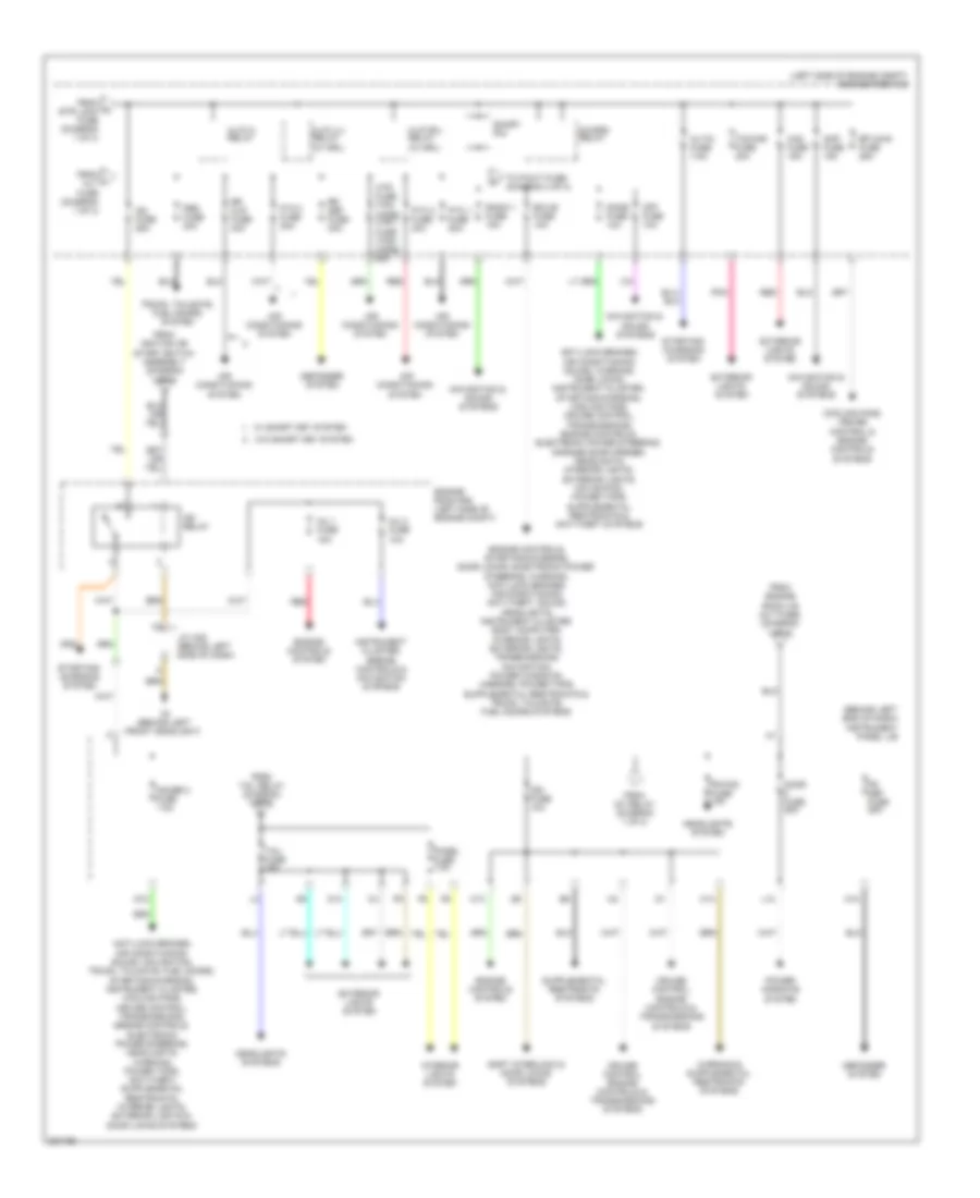
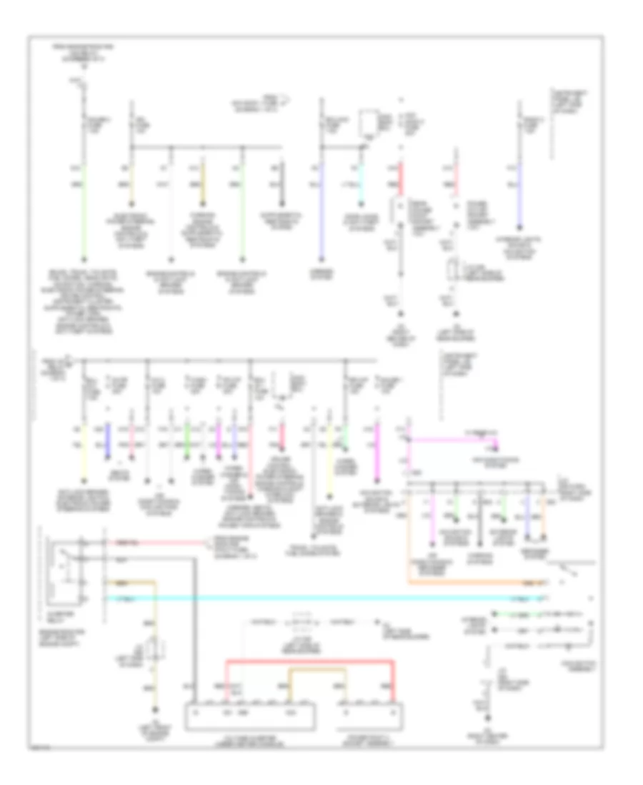
Power Distribution Wiring Diagram, Except Hybrid (1 of 3) for Toyota Highlander Limited 2010

List of elements for Power Distribution Wiring Diagram, Except Hybrid (1 of 3) for Toyota Highlander Limited 2010:
- (behind left end of dash) instrument panel j/b
- (left side of engine compt) engine room r/b
- (not used)
- A/c 1 fuse 10a
- A/c 2 fuse 10a
- A/f relay (3.5l) efi main2 relay (2.7l)
- A36
- A41
- Acc
- Acc relay
- Accd
- Air conditioning system
- Alt fuse 140a
- Am1
- Am1 fuse 7.5a
- Am2
- Am2 fuse 7.5a
- Anti-lock brakes, engine controls, cruise control, shift interlock & exterior lights systems
- B36
- Battery
- C11
- C12
- Com
- Computer data lines system
- Cruise control, transmissions & engine controls systems
- D12
- D4 (behind left kick panel)
- D51
- D62
- Door locks, anti-theft, cruise control, transmissions & engine controls systems
- Ecu ig1 fuse 10a
- Ecu ig2 fuse 7.5a
- Efi 1 fuse 10a
- Electronic power steering system
- Engine room j/b (left side of engine compt)
- Eps fuse 80a
- Etcs fuse 10a
- Exterior lights & anti-lock brakes systems
- F10
- F11
- F14
- F16
- F19
- Fr wip fuse 30a
- From ignition or starter switch assembly (diagram 1 of 3)
- Fuel opn fuse 7.5a
- G/h fuse 10a
- Gauge 1 fuse 10a
- Generator assembly
- Gnd
- H-lp (ll) relay (w/o drl)
- H-lp (rl) relay (w/o drl)
- H16
- Horn relay
- Ig1 relay
- Ig1d
- Ig2d
- Ignition or starter switch assembly (w/o smart key system)
- J/c a36 & d51 (tmc made) j/c a41 & d62 (tmmi made) (tmc made: behind left kick panel)
- L11
- Lock
- M17
- M19
- M20
- Main body ecu
- Main body ecu (w/ smart key system) (on instrument panel j/b)
- Mirrors, defogger & interior lights systems
- Mirrors, seats & power tops systems
- Navigation, sound, transmissions, cruise control, door locks, interior lights, defogger, starting/charging, exterior lights & anti-lock brakes systems
- Obd fuse 7.5a
- Off
- P/ seat fuse 30a
- Pnk
- Power switch (w/ smart key system)
- Power tops system
- Pwr relay
- R10
- R12
- Red
- Rr wip fuse 15a
- S-htr fuse 20a
- S/ roof fuse 30a
- Seats system
- Shift interlock system
- Shift interlock, cruise control, transmissions, electronic power steering & warning systems
- Ss1
- Ss2
- Ssw1
- Ssw2
- St fuse 30a
- Start
- Starting/ charging system
- Stop fuse 10a
- Str lock fuse 20a
- Tail relay
- Tmc made
- Tmmi made
- To acc sock 2 fuse (diagram 3 of 3)
- To am1 fuse (diagram 1 of 3)
- To fr fog fuse (diagram 2 of 3)
- To ig2 fuse (diagram 2 of 3)
- To ig2 relay (diagram 2 of 3)
- To instrument panel j/b (door 2 fuse) (diagram 2 of 3)
- To j/c d53 & e24 (diagram 3 of 3)
- To pbd fuse (diagram 2 of 3)
- To tail fuse (diagram 2 of 3)
- Trly
- Trunk, tailgate, fuel doors system
- W/ smart key system
- W/o smart key system
- Wash fuse 20a
- Wiper/ washer system
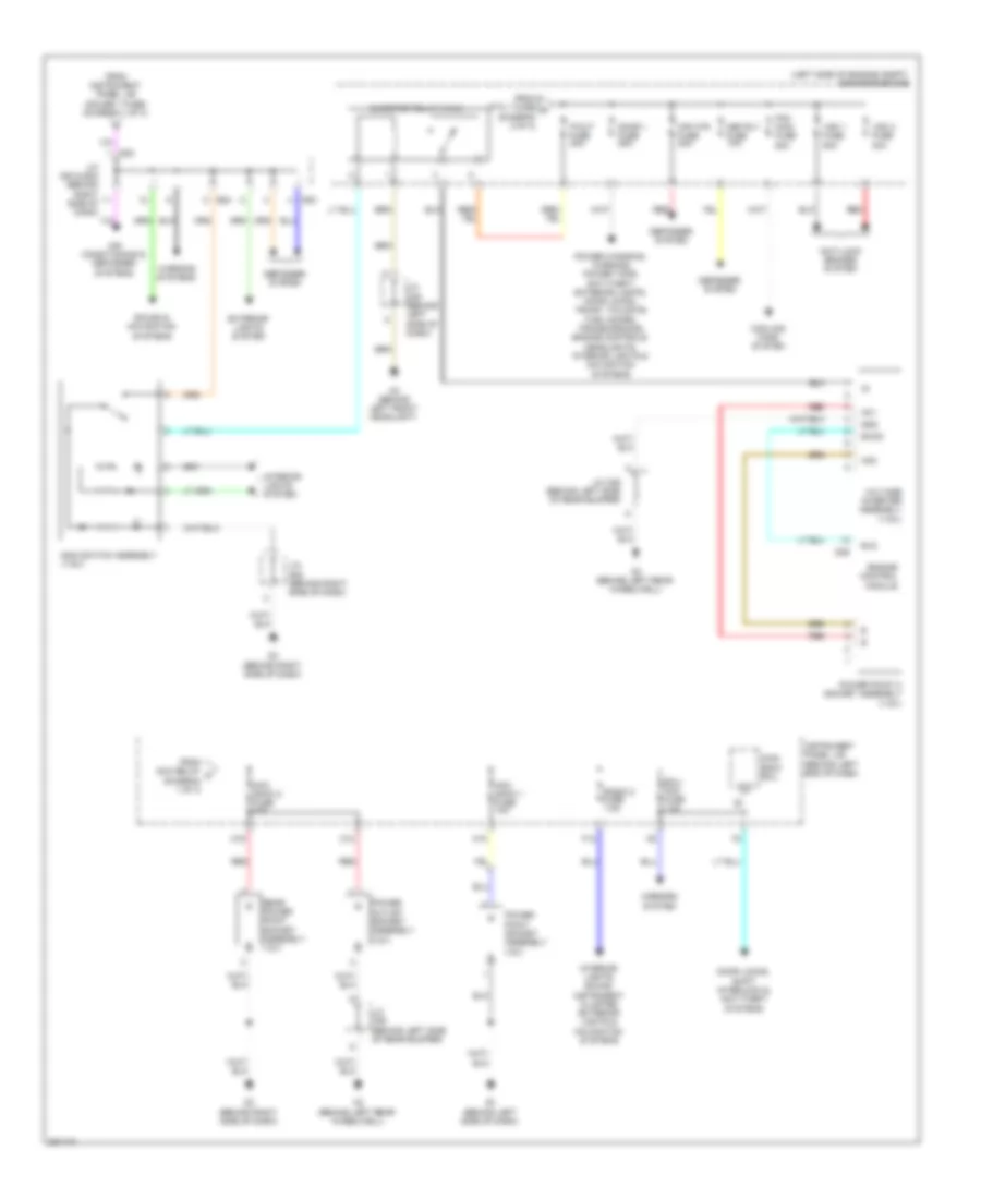
Power Distribution Wiring Diagram, Except Hybrid (2 of 3) for Toyota Highlander Limited 2010
List of elements for Power Distribution Wiring Diagram, Except Hybrid (2 of 3) for Toyota Highlander Limited 2010:
- (behind left end of dash) instrument panel j/b
- (left side of engine compt) engine room r/b
- A3 (behind left front headlight)
- Air conditioning system
- Alt-s fuse 7.5a
- Amp fuse 15a
- Cooling fans, cruise control & engine controls systems
- Crt fuse 10a
- Cruise control, engine controls & transmissions systems
- D14
- Defogger system
- Dome fuse 10a
- Door fuse 25a
- Ecu-b fuse 10a
- Efi main fuse 25a
- Engine controls system
- Engine room r/b (left side of engine compt)
- Exterior lights system
- Fr def fuse 25a
- Fr fog fuse 15a
- From alt fuse (diagram 1 of 3)
- From engine room j/b (alt fuse) (diagram 1 of 3)
- From ig1 relay (diagram 1 of 3)
- From ignition or start switch assembly (diagram 1 of 3)
- From str lock fuse (diagram 1 of 3)
- From tail relay (diagram 1 of 3)
- G12
- Gauge 2 fuse 7.5a
- H-lp (ll) relay (w/ drl)
- H-lp (rl) relay (w/ drl)
- H-lp hi relay
- Haz fuse 15a
- Headlights system
- Headlights systems
- Htr fuse (tmc made) htr 1 fuse (tmmi made) 50a
- Ig2 fuse 25a
- Ig2 relay
- Ign fuse 10a
- Inj 1 fuse 15a
- Inj 2 fuse 10a
- Instrument cluster, engine controls & navigation systems
- Interior lights system
- J/c a39 (behind left side of dash)
- L12
- M13
- M14
- M18
- Navigation & sound systems
- Panel fuse 7.5a
- Pbd fuse 30a
- Pnk
- Power windows system
- Ptc 1 fuse 50a
- Ptc 2 fuse 30a
- Ptc 3 fuse 30a
- Radio 1 fuse 15a
- Red
- Rr clr fuse 40a
- Rr def fuse 30a
- S-horn relay
- Shift interlock & door locks systems
- Short pin
- Starting/ charging system
- Tail fuse 15a
- To p/out fuse (diagram 3 of 3)
- Towing fuse 30a
- Trunk, tailgate, fuel doors system
- W/ smart key system
- W/o smart key system
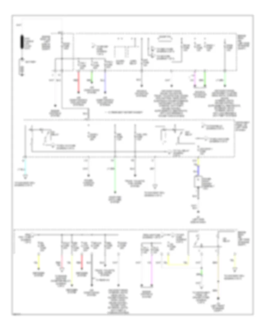
Power Distribution Wiring Diagram, Except Hybrid (3 of 3) for Toyota Highlander Limited 2010
List of elements for Power Distribution Wiring Diagram, Except Hybrid (3 of 3) for Toyota Highlander Limited 2010:
- (left side of engine compt) engine room r/b
- A3 (behind left front headlight)
- Ac1
- Ac2
- Acc
- Acc sock 1 fuse 10a
- Acc sock 2 fuse 20a
- Air conditioning & defogger systems
- Anti-lock brakes system
- Cooling fans system
- D3 (behind right side of dash)
- D36
- D53
- Def rly fuse 10a
- Defogger system
- Door 1 fuse 25a
- Door locks, shift interlock & anti-theft systems
- E1 (behind left side of dash)
- E24
- Ecu- acc fuse 7.5a
- Els
- Engine control module
- Excd
- Exterior lights system
- F12
- Fan main fuse 50a
- From acc relay d (diagram 1 of 3)
- From instrument panel j/b (gauge 1 fuse) (diagram 1 of 3)
- From ptc 1 fuse h (diagram 2 of 3)
- Gnd
- Instrument panel j/b (behind left end of dash)
- Interior lights system
- Interior lights, sound, instrument cluster, exterior lights & navigation systems
- Inverter relay (115v)
- J/c a39 (behind left side of dash)
- J/c d52 (behind right side of dash)
- J/c d53 & e24 (behind right side of dash)
- J/c o36 (behind left side of rear bumper)
- M10
- M16
- Main body ecu
- Main switch assembly (115v)
- Mir htr fuse 20a
- Mirrors system
- O12
- O2 (behind left rear wheelwell)
- P/out fuse 20a
- Power outlet socket assembly (12v)
- Power point 2 socket assembly (115v)
- Power point socket assembly (12v)
- Power windows, warning, power tops, anti-theft, exterior lights, door locks, trunk, tailgate, fuel doors, transmissions, engine controls, headlights, interior lights & navigation systems
- Radio 2 fuse 7.5a
- Rear power point socket assembly (12v)
- Red
- Sound & navigation systems
- Voltage inverter assembly (115v)
- Vsc 1 fuse 50a
- Vsc 2 fuse 30a
- Warning systems
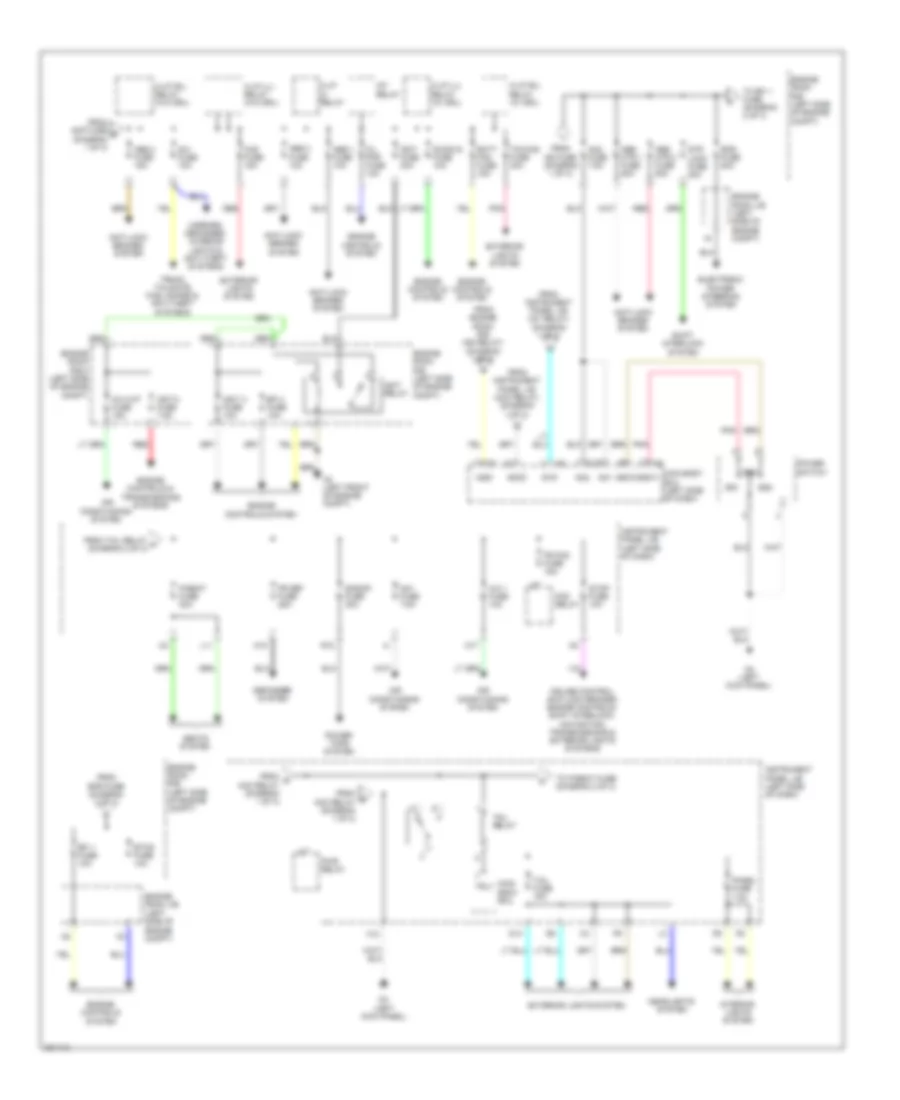
Power Distribution Wiring Diagram, Hybrid (1 of 3) for Toyota Highlander Limited 2010
List of elements for Power Distribution Wiring Diagram, Hybrid (1 of 3) for Toyota Highlander Limited 2010:
- A3 (left front of engine compt)
- Acc relay
- Acc sock 1 fuse 10a
- Air conditioning & cooling fans systems
- Air conditioning system
- Air conditioning, interior lights, headlights, power windows, door locks, cruise control, power tops, exterior lights, anti-theft & warning systems
- Amp fuse 15a
- Battery
- Computer data lines system
- Crt fuse 10a
- Dc/dc fuse 140a
- Def rly fuse 10a
- Defogger system
- Dome fuse 10a
- Door 2 fuse 25a
- Door1 fuse 25a
- E1 (left side side of dash)
- Ecu-b fuse 10a
- Engine controls system
- Engine room j/b (left side of engine compt)
- Engine room r/b (left side of engine compt)
- Fan 1 fuse 50a
- Fan 2 fuse 50a
- From a fan 1 fuse (diagram 1 of 3)
- From amp fuse c (diagram 1 of 3)
- Fuel opn fuse 7.5a
- Horn relay
- Htr fuse 50a
- Ig1 relay
- Ig2 fuse 25a
- Ig2 relay
- Inj 1 fuse 15a
- Inj 2 fuse 10a
- Instrument panel j/b (left side of dash)
- L12
- M10
- Mir htr fuse 20a
- Obd fuse 7.5a
- P/out fuse 20a
- Pbd fuse 30a
- Power point socket assembly (12v)
- Power windows system
- Radio 1 fuse 15a
- Red
- Rr clr fuse 40a
- Rr def fuse 30a
- S-horn relay
- Short pin
- Sound & navigation systems
- To abs 3 fuse (diagram 2 of 3)
- To am2 fuse (diagram 2 of 3)
- To ecu ig 2 fuse (diagram 3 of 3)
- To ecu-acc fuse (diagram 3 of 3)
- To engine room r/b (inverter relay) (diagram 3 of 3)
- To ig2 fuse (diagram 1 of 3)
- To instrument panel j/b (gauge 2 fuse) (diagram 3 of 3)
- To main body ecu (diagram 2 of 3)
- To pwr relay (diagram 2 of 3)
- To rr def fuse (diagram 1 of 3)
- To tail relay (diagram 2 of 3)
- Trunk, tailgate, fuel doors system
- W/ rear a/c
- W/ rear seat entertainment
Power Distribution Wiring Diagram, Hybrid (2 of 3) for Toyota Highlander Limited 2010
List of elements for Power Distribution Wiring Diagram, Hybrid (2 of 3) for Toyota Highlander Limited 2010:
- A/c 1 fuse 10a
- A/f relay
- A3 (left front of engine compt)
- Abs 1 fuse 10a
- Abs 2 fuse 10a
- Abs 3 fuse 15a
- Abs mtr 1 fuse 50a
- Abs mtr 2 fuse 50a
- Accd
- Air conditioning system
- Am1
- Am1 fuse 7.5a
- Am2
- Am2 fuse 7.5a
- Anti-lock brakes system
- Batt fan fuse 15a
- Cruise control, anti-lock brakes, engine controls, shift interlock, navigation, transmissions & exterior lights systems
- D14
- D4 (left kick panel)
- Dc/dc-s fuse 10a
- Defogger system
- Efi 1 fuse 10a
- Efi 3 fuse 10a
- Electronic power steering system
- Engine controls & transmissions systems
- Engine controls system
- Engine room j/b (left side of engine compt)
- Engine room r/b (left side of engine compt)
- Engine room r/b 2 (left side of engine compt)
- Eps fuse 80a
- Etcs fuse 10a
- Exterior lights system
- F10
- Fog relay
- Fr def fuse 25a
- Fr fog fuse 15a
- From amp fuse b (diagram 1 of 3)
- From d acc relay (diagram 1 of 3)
- From engine room r/b (ig2 relay) (diagram 1 of 3)
- From eps fuse (diagram 2 of 3)
- From g acc relay (diagram 1 of 3)
- From ig2 fuse (diagram 1 of 3)
- From instrument panel j/b (acc relay) (diagram 1 of 3)
- From instrument panel j/b (ig1 relay) (diagram 1 of 3)
- From tail relay m (diagram 2 of 3)
- G/h fuse 10a
- Gnd
- H-lp (ll) relay (w/ drl)
- H-lp (ll) relay (w/o drl)
- H-lp (rl) relay (w/ drl)
- H-lp (rl) relay (w/o drl)
- H-lp hi relay
- Haz fuse 15a
- Headlights system
- Ig1d
- Ig2d
- Igct 2 fuse 7.5a
- Igct 3 fuse 10a
- Igct fuse 30a
- Igct relay
- Instrument panel j/b (left side of dash)
- Interior lights system
- Inv-w/p fuse 15a
- L11
- M17
- M18
- Main body ecu
- Main body ecu (left side of dash)
- Mirrors, defogger, interior lights & anti-theft systems
- Oil pmp fuse 10a
- P/seat fuse 30a
- Panel fuse 7.5a
- Pnk
- Power switch
- Power tops system
- Pwr relay
- R12
- Red
- S/roof fuse 30a
- Seats system
- Shift interlock system
- Ss1
- Ss2
- Ssw1
- Ssw2
- Stop fuse 10a
- Str lock fuse 20a
- Tail fuse 15a
- Tail relay
- To efi 1 fuse (diagram 2 of 3)
- To p/seat fuse (diagram 2 of 3)
- Towing fuse 30a
- Trly
- Trunk, tailgate, fuel doors & anti-theft systems
Power Distribution Wiring Diagram, Hybrid (3 of 3) for Toyota Highlander Limited 2010
List of elements for Power Distribution Wiring Diagram, Hybrid (3 of 3) for Toyota Highlander Limited 2010:
- (diagram 1 of 3)
- A/c 2 fuse 10a
- A3 (left front of engine compt)
- Ac1
- Ac2
- Acc
- Acc sock 2 fuse 20a
- Air conditioning & cooling fans systems
- Air conditioning & defogger systems
- Air conditioning system
- Anti-lock brakes & engine controls systems
- Anti-lock brakes, exterior lights & electronic power steering systems
- C11
- C12
- Cruise control, electronic power steering, engine controls, warning & shift interlock systems
- D12
- D3 (right center of dash)
- D53
- Defogger system
- Door locks & anti-theft systems
- E24
- Ecu ig 1 fuse 10a
- Ecu ig 2 fuse 7.5a
- Ecu-acc fuse 7.5a
- Electronic power steering, engine controls & anti-theft systems
- Engine controls & anti-lock brakes systems
- Engine room r/b (left side of engine compt)
- Exterior lights system
- F11
- F12
- F14
- F16
- Fr wip fuse 30a
- From acc sock 1 fuse f
- From engine room r/b (ig2 relay) (diagram 1 of 3)
- From engine room r/b (p/out fuse) (diagram 1 of 3)
- From ig1 e relay (diagram 1 of 3)
- G12
- Gauge 1 fuse 10a
- Gauge 2 fuse 7.5a
- Gnd
- H16
- Ign fuse 10a
- Instrument panel j/b (left side of dash)
- Interior lights system
- Interior lights, sound & navigation systems
- Inverter relay
- J/c a58 (left side of dash)
- J/c d52 (right side of dash)
- J/c d53 & e24 (right side of dash)
- J/c o36 (left side of rear bumper)
- M14
- M16
- M19
- M20
- Main body ecu
- Main switch assembly
- Mirrors system
- Mirrors, seats, anti-lock brakes, engine controls & power tops systems
- Navigation, sound & exterior lights systems
- Navigation, sound & systems
- O12
- O2 (left side of rear bumper)
- Pnk
- Power outlet socket assembly (12v)
- Power point 2 socket assembly
- R10
- Radio 2 fuse 7.5a
- Rear power point socket assembly (12v)
- Red
- Rr wip fuse 15a
- S-htr fuse 20a
- Seats system
- Trunk, tailgate, fuel doors system
- Voltage inverter (under center console)
- W/ rear a/c
- Warning systems
- Wash fuse 20a
- Wiper/ washer & air condi- tioning systems
- Wiper/ washer system