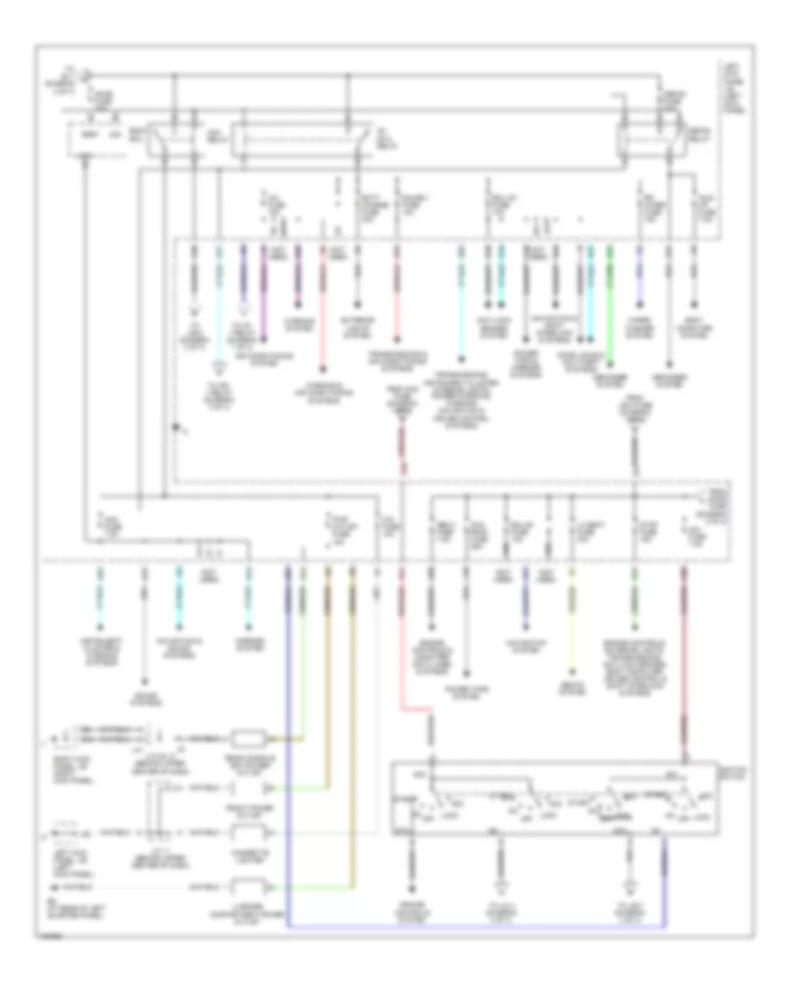
POWER DISTRIBUTION
Power Distribution Wiring Diagram (1 of 3) for Toyota Land Cruiser 2004

List of elements for Power Distribution Wiring Diagram (1 of 3) for Toyota Land Cruiser 2004:
- (not used)
- A39
- A49
- A50
- A58
- A59
- A60
- A63
- Abs 1 fuse 50a
- Abs 2 fuse 40a
- Abs mtr1 relay
- Abs mtr2 relay
- Abs sol relay
- Air conditioning system
- Alt fuse 140a
- Alt s fuse 7.5a
- Am2 fuse 15a
- Amp fuse 30a
- B11
- B24
- B39
- B47
- B49
- B50
- B58
- B60
- B61
- B62
- B63
- B65
- B67
- B69
- B70
- B72
- Bat fuse 30a
- Battery
- Body ecu
- Ee (at left front fender apron)
- Efi or ecd 1 fuse 15a
- Efi or ecd relay
- Engine controls, transmissions & cruise control systems
- Engine room j/b (on left inner fender panel)
- Engine room r/b
- Etcs fuse 10a
- Exterior lights system
- Exterior lights, headlights & anti-theft systems
- F15
- F16
- F17
- F18
- F19
- Fr fog fuse 15a
- Fr fog relay
- Fr ig fuse 10a
- From j/b 1 fuse diagram 1 of 3
- From left kick panel j/b (diagram 2 of 3)
- Fusible link block (on left side of engine compt, near battery)
- Haz trn fuse 15a
- Head hi relay
- Head relay
- Horn fuse 10a
- Horn relay
- Htr fuse 50a
- Ig1 relay
- Interior lights & instrument cluster systems
- J/b 1 fuse 120a
- J/b 2 fuse 120a
- J/b 3 fuse 120a
- Left kick panel j/b (left kick panel)
- Main fuse 120a
- Mir fuse (diagram 1 of 3)
- Mir htr fuse 15a
- Mir htr relay
- Nca
- Panel fuse 7.5a
- Pw fuse (diagram 3 of 3)
- Rr htr fuse 10a
- Rr htr relay
- Short pin (a)
- Short pin (b)
- Sound systems
- Starter fuse 30a
- Starting/ charging & engine control systems
- Starting/ charging system
- Tail fuse 15a
- Tail relay
- To ecu b2 (diagram 3 of 3)
- To left kick panel j/b (diagram 2 of 3)
- To stop fuse (diagram 2 of 3)
- Towing brk fuse 30a
- Towing fuse 30a
- Towing tail fuse 30a
- Trly
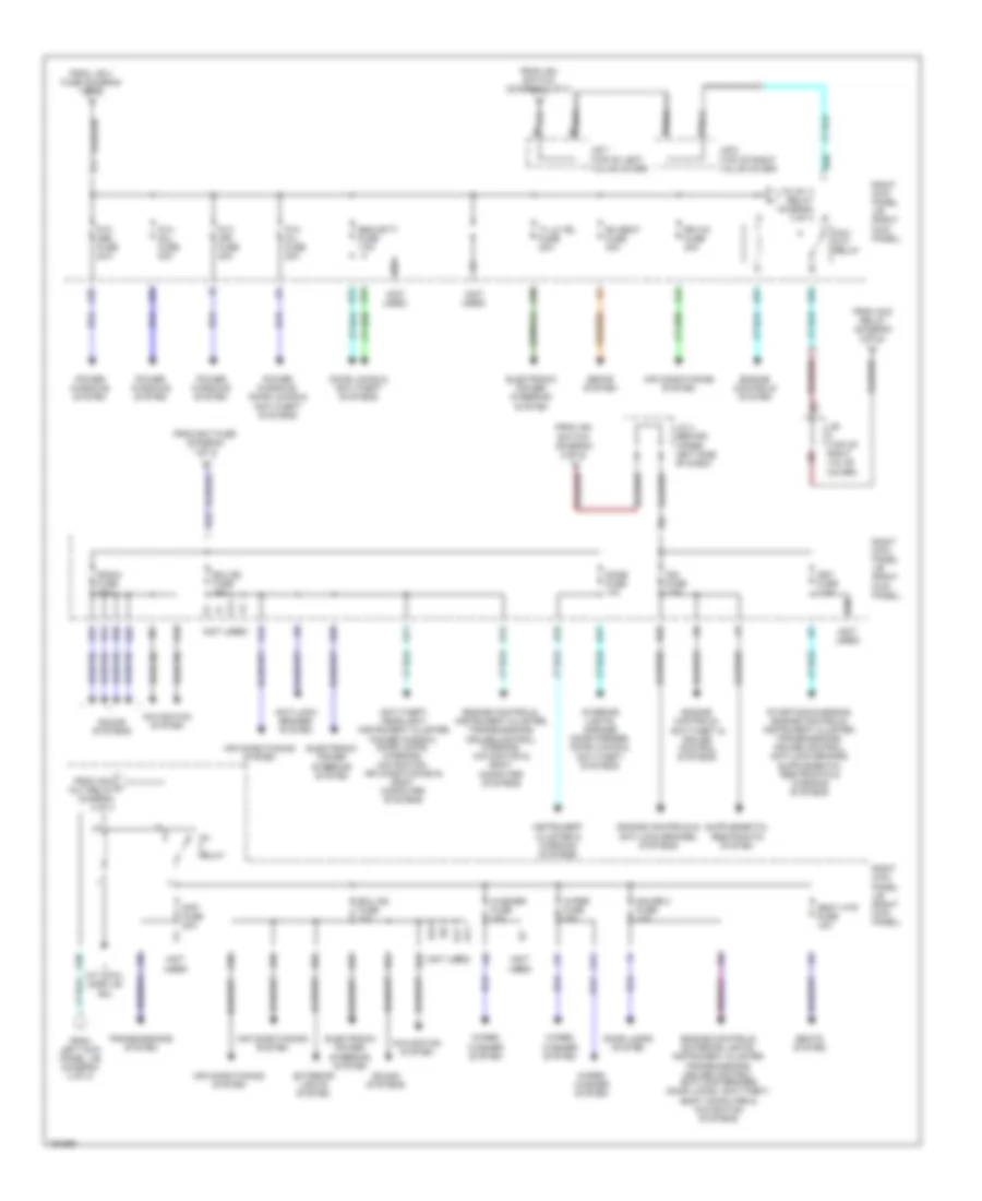
Power Distribution Wiring Diagram (2 of 3) for Toyota Land Cruiser 2004
List of elements for Power Distribution Wiring Diagram (2 of 3) for Toyota Land Cruiser 2004:
- (not used)
- A/c fuse 15a
- A10
- Acc
- Acc fuse 7.5a
- Acc relay
- Air conditioning system
- Am1
- Am1 fuse 7.5a
- Am2
- Anti-lock brakes system
- B18
- Batt charge fuse 30a
- Bdr1
- Bm (at rear of left quarter panel)
- Body computer system
- Body ecu
- Cig fuse 15a
- Cigarette lighter
- D10
- D11
- D14
- D16
- D17
- D19
- D20
- D21
- D24
- D25
- D31
- Defog fuse 20a
- Defog relay
- Defogger system
- Door fuse 25a
- Door locks & anti-theft systems
- E31
- E32
- E37
- E39
- E40
- E41
- Ecu b1 fuse 10a
- Ecu ig1 fuse 10a
- Engine controls & computer data lines systems
- Engine controls system
- Engine controls, exterior lights, transmissions, anti-lock brakes, body computer, cruise control & shift interlock systems
- Exterior lights system
- From j/b 2 fuse (diagram 1 of 3)
- From am2 fuse (diagram 1 0f 3)
- From door fuse (diagram 2 of 3)
- Front power outlet
- Gauge 1 fuse 10a
- I11
- Idle up fuse 7.5a
- Ig1
- Ig1 no.2 relay
- Ig2
- Ignition switch
- Instrument cluster & warning systems
- J/c 11 (behind upper center of dash)
- J/c 9 & 10 (behind upper center of dash)
- J10
- K23
- K31
- L10
- L19
- Left kick panel j/b (left kick panel)
- Lh seat fuse 30a
- Lock
- Lock off
- Luggage compartment power outlet
- Mirrors system
- Navigation & shift interlock systems
- Navigation & sound systems
- Navigation system
- Obd 2 fuse 7.5a
- Off
- Power tops & mirrors systems
- Power tops system
- Pwr outlet fuse 15a
- Q16
- Q17
- Q21
- Q44
- Q57
- Q64
- Q65
- Q77
- Rear console box power outlet
- Right kick panel j/b (right kick panel)
- Rr wiper fuse 15a
- Seats system
- Sig
- Sound systems
- St2
- Start
- Stop fuse 15a
- Sun roof fuse 25a
- To am 1 f (diagram 2 of 3)
- To ig1 1 relay (diagram 1 of 3)
- To ign 1 relay (diagram 3 of 3)
- To j/b 6 (diagram 3 of 3)
- To j/b 7 (diagram 3 of 3)
- To j/c 4 (diagram 3 of 3)
- Transmissions & air conditioning systems
- Transmissions, instrument cluster, interior lights, power windows, warning, navigation & cruise control systems
- Warning & air conditioning systems
- Warning system
- Wiper/ washer system
Power Distribution Wiring Diagram (3 of 3) for Toyota Land Cruiser 2004
List of elements for Power Distribution Wiring Diagram (3 of 3) for Toyota Land Cruiser 2004:
- (not used)
- Acc cut relay
- Air conditioning system
- Anti-lock brakes system
- Anti-theft, headlight, instrument cluster, power window, door locks, warning, navigation, air conditioning & body computer systems
- B11
- B22
- B25
- D14
- D24
- D29
- D31
- D36
- D37
- D38
- D39
- Diff fuse 20a
- Dome fuse 10a
- Door locks & anti-theft systems
- Door locks system
- E16
- E32
- E33
- Ecu b2 fuse 10a
- Ecu ig2 fuse 10a
- Electronic power steering system
- Engine controls & anti-lock brakes, systems
- Engine controls system
- Engine controls, anti-theft & cruise control systems
- Engine controls, exterior lights, instrument cluster, transmissions, cruise control, anti-lock brakes, door locks, anti-theft, body computer & navigation systems
- Engine controls, instrument cluster, transmissions, cruise control, warning, navigation & body computer systems
- Exterior lights system
- From acc l cut relay diagram 3 of 3
- From acc relay (diagram 2 of 3)
- From bat fuse (diagram 1 of 3)
- From ign switch (diagram 2 of 3)
- From j/b 3 fuse (diagram 1 of 3)
- From left kick panel j/b (diagram 2 of 3)
- G11
- Gauge 2 fuse 10a
- I10
- I11
- Ig1 relay
- Ign fuse 7.5a
- Ii (at cowl side j/b rh)
- Instrument cluster & warning systems
- Interior lights, garage door opener, door locks & anti-theft systems
- J/b (top of right valve cover)
- J/b 6 (top of right valve cover)
- J/b 7 (top of left valve cover)
- J/c 4 (behind upper left side of dash)
- K11
- K16
- K19
- K23
- K24
- K33
- K35
- K37
- K39
- K41
- K42
- Met fuse 7.5a
- Navigation system
- P/w (fl) fuse 20a
- P/w (fr) fuse 20a
- P/w (rl) fuse 20a
- P/w (rr) fuse 20a
- Power windows system
- Power windows, door locks & anti-theft systems
- Q17
- Q39
- Q44
- Q45
- Q50
- Q51
- Q52
- Q71
- Q72
- Radio fuse 10a
- Rh seat fuse 30a
- Right kick panel j/b (right kick panel)
- Rr a/c fuse 30a
- Seat htr fuse 15a
- Seats system
- Security fuse 7.5a
- Sound systems
- Til & tel fuse 20a
- To ig1 3 relay diagram 3 of 3
- Transmissions system
- Washer fuse 15a
- Wiper fuse 25a
- Wiper/ washer system