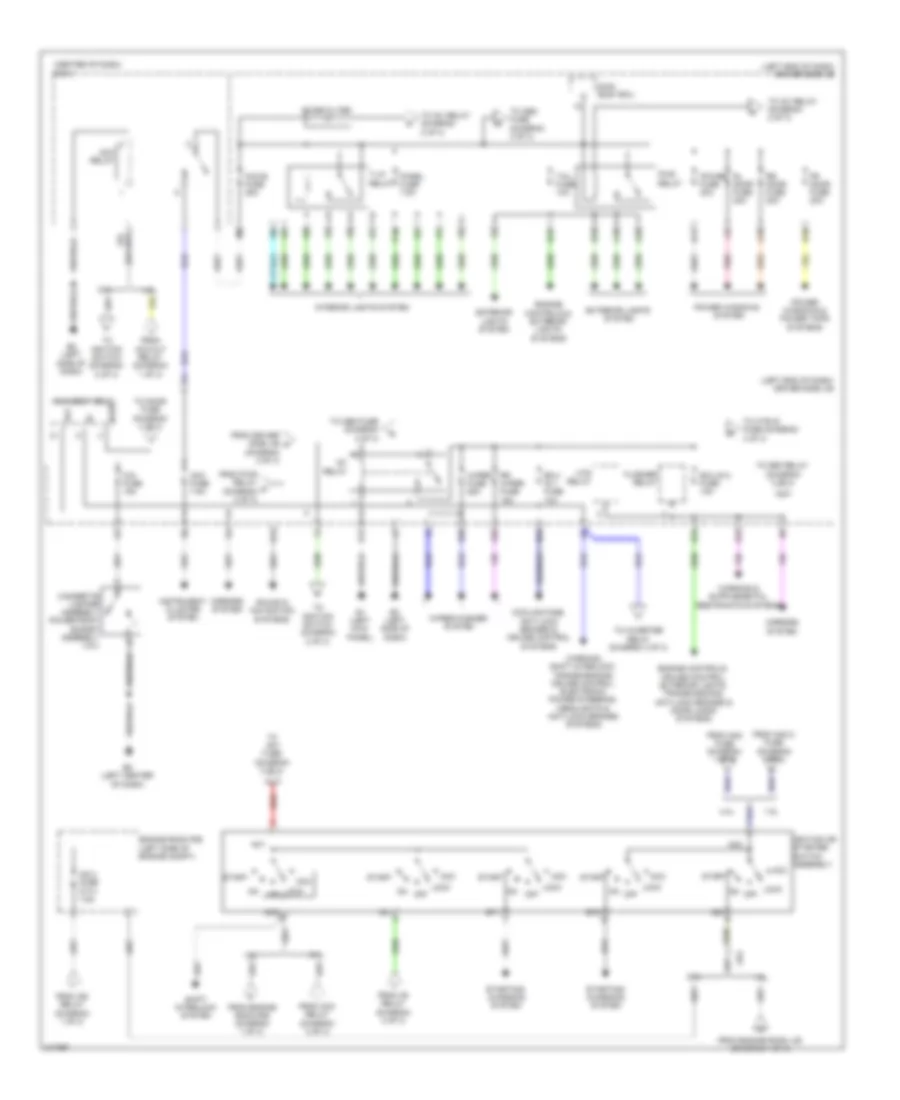
POWER DISTRIBUTION
Power Distribution Wiring Diagram (1 of 3) for Toyota Matrix S 2011

List of elements for Power Distribution Wiring Diagram (1 of 3) for Toyota Matrix S 2011:
- (center of dash) r/b 8
- (left end of dash) driver side j/b
- (left side of dash) j/c a33
- (left side of engine compt) engine room j/b
- (left side of engine compt) engine room r/b
- 1.8l
- 2.4l
- A1 (left front of engine compt)
- Abs 1 fuse 50a
- Abs 3 fuse 30a
- Acc cut relay (1.8l)
- Ae1
- Ae2
- Air conditioning & anti-theft systems
- Air conditioning system
- Alt fuse 120a
- Alt-s fuse 7.5a
- Am2 2 fuse (1.8l) 7.5a
- Am2 fuse 30a
- Anti-lock brakes system
- B30
- Battery
- Becu
- C/opn relay
- Cds fan fuse 30a
- Cooling fans system
- Cruise control, transmissions & engine controls systems
- Dcc short pin
- Dimmer relay
- Dome fuse 10a
- E16
- E21
- Ecu-b fuse 10a
- Ecu-b2 fuse 10a
- Efi main fuse 20a
- Efi main relay
- Electronic power steering system
- Engine controls & transmissions systems
- Engine controls system
- Engine controls, cruise control & transmissions systems
- Eps fuse 60a
- Etcs fuse 10a
- Exterior lights system
- From abs 3 fuse (diagram 1 of 3)
- From am2 fuse (diagram 1 of 3)
- H-lp main fuse 50a
- H-lp relay
- H12
- Horn fuse 10a
- Horn relay
- Htr fuse 50a
- Htr sub 1 fuse 30a
- Htr sub 3 fuse 30a
- Ig2 fuse 15a
- Ig2 relay
- Ign fuse 7.5a
- Instrument cluster, interior lights, anti-theft & door locks systems
- Main body ecu
- Meter fuse 7.5a
- Navigation & sound systems
- P/i fuse 50a
- Pnk
- Pwr outlet/ inverter fuse 15a
- Rad 1 fuse 15a
- Rdi fan fuse 40a
- Red
- Starting/ charging system
- To acc relay (diagram 2 of 3)
- To am2 2 fuse (diagram 1 of 3)
- To driver side j/b (diagram 3 of 3)
- To h-lp man fuse (diagram 1 of 3)
- To ig2 2 fuse (diagram 2 of 3)
- To ignition switch (diagram 2 of 3)
- To inverter relay (diagram 3 of 3)
- Transmissions, instrument cluster, anti-lock brakes, starting/charging, cruise control, engine controls, electronic power steering, headlights, exterior lights, warning & interior lights systems
- Turn- haz fuse 10a
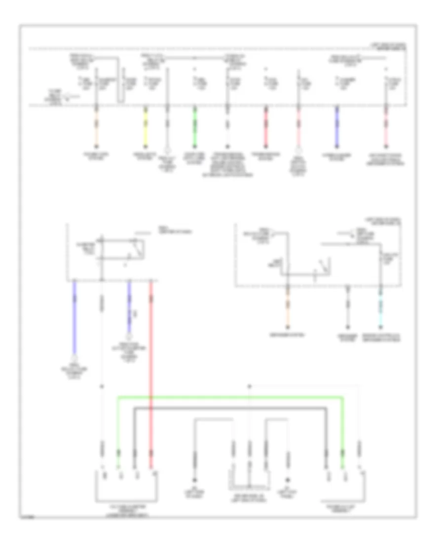
Power Distribution Wiring Diagram (2 of 3) for Toyota Matrix S 2011
List of elements for Power Distribution Wiring Diagram (2 of 3) for Toyota Matrix S 2011:
- (center of dash) r/b 8
- (left end of dash) driver side j/b
- 1.8l
- 2.4l
- A10
- A19
- A25
- A29
- Acc
- Acc fuse 7.5a
- Acc relay
- Acc-b fuse 25a
- Ae4
- Altb
- Am1
- Am2
- B15
- B19
- B24
- B33
- B36
- Cig fuse 15a
- Cigarette lighter assembly power point socket assembly (12v)
- Cooling fans, anti-lock brakes & cruise control systems
- D14
- E1 (left kick panel)
- E17
- E2 (left side of dash)
- E5 (left center of dash)
- Ecu- ig 1 fuse 10a
- Ecu-ig 2 fuse 10a
- Engine controls & exterior lights systems
- Engine controls, cruise control, exterior lights, transmissions, anti-lock brakes & door locks systems
- Engine room r/b (left side of engine compt)
- Exterior lights system
- Flasher relay
- Fr door fuse 20a
- From acc cut relay (diagram 1 of 3)
- From acc relay (diagram 2 of 3)
- From am2 2 fuse (diagram 1 of 3)
- From am2 fuse (diagram 1 of 3)
- From driver side j/b n (diagram 2 of 3)
- From engine room j/b (diagram 1 of 3)
- From engine room r/b (diagram 1 of 3)
- From ig1 relay (diagram 2 of 3)
- From ig2 relay (diagram 1 of 3)
- From pwr relay m (diagram 2 of 3)
- H10
- H11
- Htr relay
- Ig1
- Ig1 relay
- Ig2
- Ig2 2 fuse (2.4l) 7.5a
- Ignition or starter switch assembly
- Instrument cluster system
- Interior lights system
- Lock
- Main body ecu
- Mirrors system
- Noise filter
- Off
- On off
- P10
- Panel fuse 7.5a
- Pnk
- Power fuse 30a
- Power windows & power tops systems
- Power windows system
- Pwr relay
- Red
- Rl door fuse 20a
- Rr door fuse 20a
- Rr wiper fuse 15a
- S15
- Shift interlock system
- Sound & navigation systems
- St1
- St2
- Start
- Starting/ charging system
- T-lp relay
- Tail fuse 10a
- To am1 fuse (diagram 3 of 3)
- To def relay (diagram 3 of 3)
- To door fuse (diagram 3 of 3)
- To htr-ig fuse (diagram 3 of 3)
- To ig1 relay (diagram 2 of 3)
- To ignition switch (diagram 2 of 3)
- To inverter relay (diagram 3 of 3)
- To obd fuse (diagram 3 of 3)
- Warning, shift interlock, transmissions, cruise control, electronic power steering, headlights & anti-lock brakes systems
- Wiper fuse 25a
- Wiper/washer system
Power Distribution Wiring Diagram (3 of 3) for Toyota Matrix S 2011
List of elements for Power Distribution Wiring Diagram (3 of 3) for Toyota Matrix S 2011:
- (left end of dash) driver side j/b
- 4wd fuse 7.5a
- Ac1
- Ac2
- Acc1
- Acc2
- Ae4
- Air conditioning, cooling fans & defogger systems
- Am1 fuse 7.5a
- B18
- Computer data lines system
- Def fuse 30a
- Def relay
- Defogger system
- Door fuse 25a
- Driver side j/b (left end of dash)
- E1 (left kick panel)
- E17
- E2 (left side of dash)
- E28
- Engine controls & defogger systems
- Fr fog fuse 15a
- From alt fuse (diagram 1 of 3)
- From def fuse (diagram 3 of 3)
- From ecu-ig 1 fuse (diagram 2 of 3)
- From ecu-ig 2 fuse (diagram 2 of 3)
- From ecu-ig 2 fuse t (diagram 2 of 3)
- From ig1 relay (diagram 2 of 3)
- From ignition switch (diagram 2 of 3)
- From main body ecu p (diagram 2 of 3)
- From pwr outlet/inverter fuse (diagram 1 of 3)
- From t-lp relay q (diagram 2 of 3)
- Gnd
- Headlights system
- Htr-ig fuse 10a
- Inverter relay (115v)
- M11
- Mir htr fuse 10a
- Obd fuse 7.5a
- Power outlet assembly
- Power tops system
- Q10
- Q12
- R/b 8 (center of dash)
- Red
- Stop fuse 10a
- Sunroof fuse 20a
- To def relay (diagram 3 of 3)
- Transmissions system
- Transmissions, anti-lock brakes, cruise control, engine controls, shift interlock & exterior lights systems
- Voltage inverter assembly (under driver's seat)
- Washer fuse 15a
- Wiper/washer system