POWER DISTRIBUTION
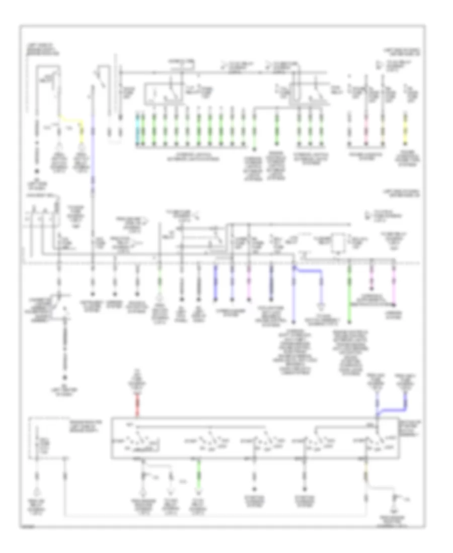
Power Distribution Wiring Diagram (1 of 3) for Toyota Matrix XRS 2009

List of elements for Power Distribution Wiring Diagram (1 of 3) for Toyota Matrix XRS 2009:
- (left end of dash) driver side j/b
- (left side of dash) j/c a33
- (left side of engine compt) engine room j/b
- (left side of engine compt) engine room r/b
- 1.8l
- 2.4l
- A1 (left front of engine compt)
- Abs 1 fuse 50a
- Abs 3 fuse 30a
- Acc cut relay (1.8l)
- Air conditioning & anti-theft systems
- Air conditioning system
- Alt fuse 120a
- Alt-s fuse 7.5a
- Am2 2 fuse (1.8l) 7.5a
- Am2 fuse (2.4l) 30a
- Amp fuse 30a
- Anti-lock brakes system
- B30
- Battery
- C/opn relay
- C15
- Cds fan fuse 30a
- Cooling fans system
- Cruise control & transmissions & engine controls systems
- Dcc short pin
- Dimmer relay
- Dome fuse 10a
- E16
- E21
- Ecu-b fuse (1.8l) 10a
- Ecu-b2 fuse 10a
- Efi main fuse 20a
- Efi main relay
- Electronic power steering system
- Engine controls system
- Engine controls, cruise control & transmissions systems
- Eps fuse 60a
- Etcs fuse 10a
- Exterior lights system
- From abs 3 fuse (diagram 1 of 3)
- From am2 fuse (diagram 1 of 3)
- H-lp main fuse 50a
- H-lp relay
- Horn fuse 10a
- Horn relay
- Htr fuse 50a
- Htr sub 1 fuse 30a
- Htr sub 3 fuse 30a
- Ig2 fuse 15a
- Ig2 relay
- Ign fuse 7.5a
- Instrument cluster, interior lights, anti-theft & door locks systems
- Meter fuse 7.5a
- Navigation & sound systems
- P/i fuse 50a
- Pnk
- Pwr outlet/ inverter fuse 15a
- Rad 1 fuse 15a
- Rdi fan 40a
- Red
- Sound systems
- Starting/ charging system
- To acc relay (diagram 2 of 3)
- To am2 2 fuse (diagram 1 of 3)
- To driver side j/b (diagram 3 of 3)
- To fuse ig2 2 (diagram 2 of 3)
- To h-lp man fuse (diagram 1 of 3)
- To ignition switch (diagram 2 of 3)
- To pwr outlet relay (diagram 3 of 3)
- Transmissions & computer data lines systems
- Turn- haz fuse 10a
Power Distribution Wiring Diagram (2 of 3) for Toyota Matrix XRS 2009
List of elements for Power Distribution Wiring Diagram (2 of 3) for Toyota Matrix XRS 2009:
- (left end of dash) driver side j/b
- (left side of engine compt) engine room r/b
- 1.8l
- 2.4l
- A10
- A19
- A25
- A29
- Acc
- Acc fuse 7.5a
- Acc relay
- Acc-b fuse 25a
- Altb
- Am1
- Am2
- B15
- B19
- B24
- B33
- B36
- Cig fuse 15a
- Cigarette lighter assembly power point socket assembly
- Cooling fans, anti-lock brakes & cruise control systems
- D14
- E1 (left kick panel)
- E17
- E2 (left side of dash)
- E5 (left center of dash)
- Ecu- ig 1 fuse 10a
- Ecu-ig 2 fuse 10a
- Engine controls, cruise control, exterior lights, transmissions, anti-lock brakes, navigation, sound, starting/ charging & door locks systems
- Engine controls, interior lights & exterior lights systems
- Engine room r/b (left side of engine compt)
- Flasher relay
- Fr door fuse 20a
- From acc cut relay (diagram 1 of 3)
- From am2 2 fuse (diagram 1 of 3)
- From am2 fuse (diagram 1 of 3)
- From driver side j/b n (diagram 2 of 3)
- From engine room r/b (diagram 1 of 3)
- From ig2 relay (diagram 1 of 3)
- From ignition switch (diagram 2 of 3)
- From pwr relay m (diagram 2 of 3)
- H10
- H11
- Htr relay
- Ig1
- Ig1 relay
- Ig2
- Ig2 2 fuse (2.4l) 7.5a
- Ignition or starter switch assembly
- Instrument cluster system
- Interior lights & exterior lights systems
- Lock
- Main body ecu
- Mirrors system
- Noise filter
- Off
- On off
- P10
- Panel fuse 7.5a
- Pnk
- Power fuse 30a
- Power windows & power tops systems
- Power windows system
- Pwr relay
- Red
- Rl door fuse 20a
- Rr door fuse 20a
- Rr wiper fuse 15a
- S15
- Sound & navigation systems
- St1
- St2
- Start
- Starting/ charging system
- T-lp relay
- Tail fuse 10a
- To acc relay (diagram 2 of 3)
- To am1 fuse (diagram 3 of 3)
- To def relay (diagram 3 of 3)
- To door fuse (diagram 3 of 3)
- To htr-ig fuse (diagram 3 of 3)
- To ig1 relay (diagram 2 of 3)
- To main switch assembly (diagram 3 of 3)
- To obd fuse (diagram 3 of 3)
- Warning, interior lights & exterior lights systems
- Warning, shift interlock, anti-theft, transmissions, cruise control, electronic power steering, headlights, anti-lock brakes & computer data lines systems
- Wiper fuse 25a
- Wiper/washer system
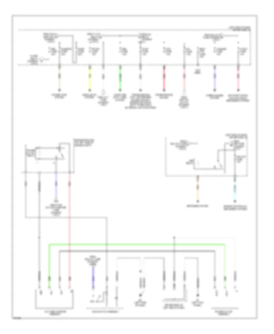
Power Distribution Wiring Diagram (3 of 3) for Toyota Matrix XRS 2009
List of elements for Power Distribution Wiring Diagram (3 of 3) for Toyota Matrix XRS 2009:
- (left end of dash) driver side j/b
- (not used)
- 2 of 3)
- 4wd fuse 7.5a
- Ac1
- Ac2
- Acc
- Acc1
- Acc2
- Air conditioning, cooling fans & defogger systems
- Am1 fuse 7.5a
- B18
- Computer data lines system
- Def fuse 30a
- Def relay
- Defogger system
- Door fuse 25a
- Driver side j/b (left end of dash)
- E1 (left kick panel)
- E17
- E2 (left side of dash)
- E28
- Engine controls & defogger systems
- Engine room r/b (on left side of engine compt)
- Fr fog fuse 15a
- From alt fuse (diagram 1 of 3)
- From def fuse (diagram 3 of 3)
- From ecu-ig 1 fuse (diagram 2 of 3)
- From ecu-ig 2 fuse (diagram 2 of 3)
- From ecu-ig 2 fuse t (diagram 2 of 3)
- From ig1 relay (diagram
- From ignition switch (diagram 2 of 3)
- From main body ecu p (diagram 2 of 3)
- From pwr outlet/inverter fuse (diagram 1 of 3)
- From t-lp relay q (diagram 2 of 3)
- Gnd
- Headlights system
- Htr-ig fuse 10a
- M11
- Main switch assembly
- Mir htr fuse 10a
- Obd fuse 7.5a
- Power outlet assembly
- Power outlet relay
- Power tops system
- Q10
- Q12
- Red
- Seat htr fuse 15a
- Stop fuse 10a
- Sunroof fuse 20a
- To def relay (diagram 3 of 3)
- Transmissions system
- Transmissions, anti-lock brakes, cruise control, engine controls, shift interlock & exterior lights systems
- Voltage inverter assembly
- Washer fuse 15a
- Wiper/washer system