POWER DISTRIBUTION
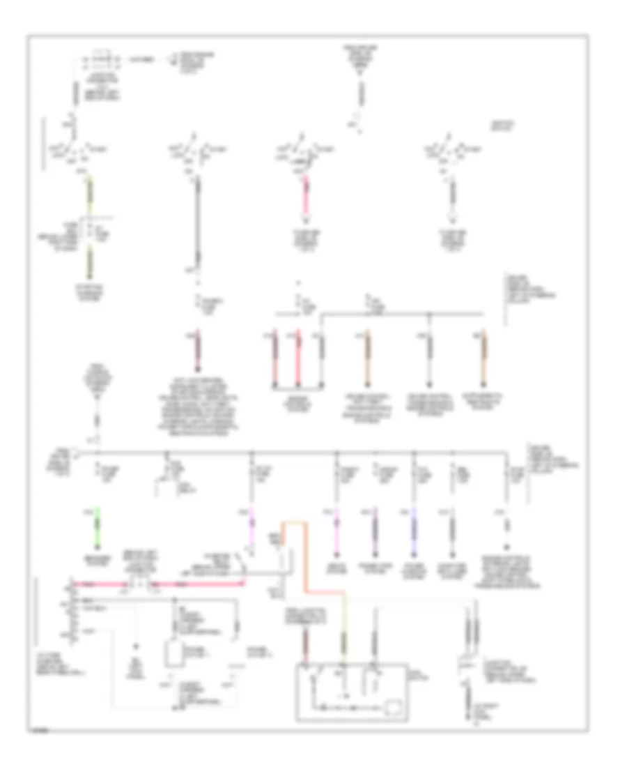
Power Distribution Wiring Diagram (1 of 3) for Toyota Sienna CE 2004

List of elements for Power Distribution Wiring Diagram (1 of 3) for Toyota Sienna CE 2004:
- (behind dash, left of steering column) driver side j/b
- (behind upper left side of dash) j/c 18
- (on left side of engine compt, inside engine room j/b) fusible link block
- Abs 1 fuse 50a
- Abs 2 fuse 30a
- Acc
- Acc relay
- Air conditioning & defogger systems
- Air conditioning system
- Air conditioning, defogger & cooling fans systems
- Air conditioning, mirrors & shift interlock systems
- Alt fuse 140a
- Am1 fuse 7.5a
- Anti-lock brakes
- Anti-lock brakes system
- Automatic a/c
- Battery
- Bh (at left "b" pillar)
- Body ecu
- Cig fuse 15a
- Cigarette lighter
- Cooling fans & air conditioning systems
- Cruise control system
- Def fuse 40a
- Defogger system
- Ecu acc fuse 7.5a
- Ecu-ig fuse 10a
- Exterior lights systems
- F10
- F11
- F12
- F13
- F14
- Fan fuse 50a
- From ig1 relay (diagram 1 of 3)
- From ignition switch (diagram 2 of 3)
- Front power outlet
- Garage door opener, interior lights & instrument cluster systems
- Gauge1 fuse 10a
- H29
- Htr fuse 10a
- Htr fuse 50a
- Ie (at left kick panel)
- Ig (at right kick panel)
- Ig1 relay
- Ign
- Instrument cluster, garage door opener, mirrors & power tops systems
- Interior lights system
- K18 pnk
- L-psd fuse 30a
- L23
- L26 red
- L8 pnk
- Manual a/c
- Navigation & sound systems
- Panel fuse 10a
- Pbd fuse 30a
- Pnk
- Power windows system
- Pwr outlet fuse 15a
- Pwr relay
- R-psd fuse 30a
- R/b 3 (in engine room j/b)
- Rad 2 fuse 7.5a
- Rear power outlet
- Red
- Relay
- Rr a/c fuse 40a
- Rr wip fuse 15a
- Rse fuse 7.5a
- S-htr fuse 15a
- Seats
- Seats system
- Shift interlock system
- St fuse 30a
- Starting/ charging system
- Starting/charging, anti-lock brakes, exterior lights, transmissions, cruise control, trunk, tailgate, fuel doors, navigation & sound systems
- System
- Tail
- Tail fuse 10a
- To acc relay (diagram 1 of 3)
- To driver side j/b (diagram 2 of 3)
- To engine room j/b (diagram 3 of 3)
- To ignition switch (diagram 2 of 3)
- To main switch (diagram 2 of 3)
- Trunk, tailgate, fuel doors system
- Wip fuse 30a
- Wiper/washer system
- Wsh fuse 20a
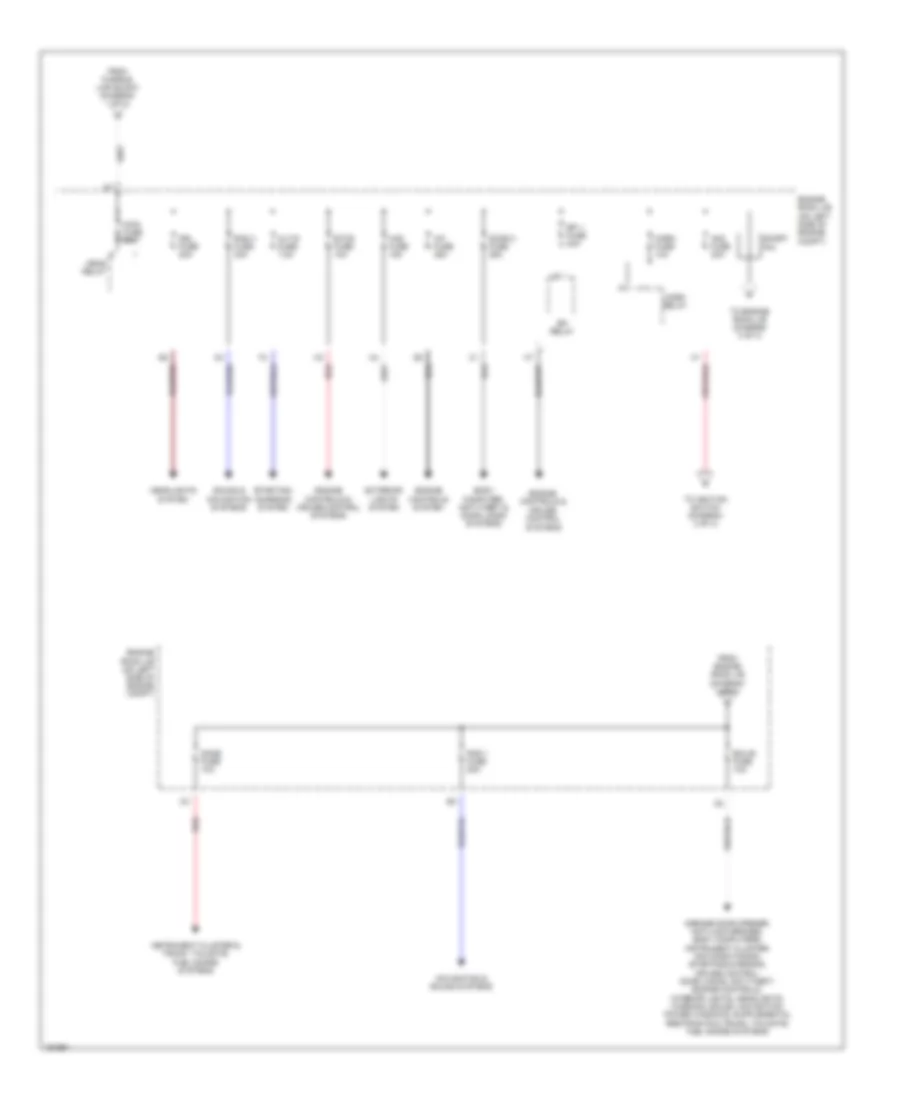
Power Distribution Wiring Diagram (2 of 3) for Toyota Sienna CE 2004
List of elements for Power Distribution Wiring Diagram (2 of 3) for Toyota Sienna CE 2004:
- (at right kick panel) ig
- (behind left end of dash) junction connector 11 & 12
- (in body harness, in left quarterpanel) b6
- Ac inv fuse 15a
- Ac1
- Ac2
- Acc
- Am1
- Am2
- B6 (in body harness, in left quarterpanel)
- Bh (left kick panel)
- C16
- Computer data lines system
- Cruise control, anti-theft, transmissions &
- Cruise control, transmissions & engine controls systems
- Defogger system
- Driver side j/b (behind dash, left of steering column)
- Engine controls system
- Engine controls systems
- Engine controls, exterior lights, anti-lock brakes, cruise control, shift interlock & transmissions systems
- Fog fuse 15a
- Fog relay
- Fr def fuse 15a
- From driver h
- From driver side j/b (diagram 1 of 3)
- From engine room j/b (diagram 3 of 3)
- From fusible link block (diagram 1 of 3)
- From junction connector j18 (diagram 1 of 3)
- Fuse box (behind lower right side of dash)
- Gauge 2 fuse 7.5a
- H18 red
- H27
- Ig1
- Ig2
- Ign fuse 7.5a
- Ignition switch
- Inj fuse 15a
- Inverter relay (behind upper left side of dash)
- J11
- J12
- Junction connector 3 & 4 (behind left end of dash)
- Junction connector j20 (behind upper left side of dash)
- K12
- K16
- K21
- K33
- Lock
- Main switch
- Obd fuse 7.5a
- Off
- P/seat fuse 30a
- P/w fuse 25a
- P10
- Pnk
- Power outlet 1
- Power outlet 2
- Power tops system
- Power windows system
- R12
- S/roof fuse 25a
- Seats system
- Side j/b (diagram 1 of 3)
- St fuse 7.5a
- St2
- Start
- Starting/ charging system
- Stop fuse 10a
- To driver side j/b (diagram 1 of 3)
- Voltage inverter (above left rear wheelwell)
Power Distribution Wiring Diagram (3 of 3) for Toyota Sienna CE 2004
List of elements for Power Distribution Wiring Diagram (3 of 3) for Toyota Sienna CE 2004:
- A/f fuse 25a
- Alt-s fuse 7.5a
- Am2 fuse 30a
- Body computer, anti-theft & door locks systems
- Dome fuse 10a
- Door 2 fuse 25a
- Drl fuse 20a
- Ecu-b fuse 10a
- Efi 1 fuse 20a
- Efi relay
- Engine controls & cruise control systems
- Engine controls system
- Engine room j/b (on left side of engine compt)
- Etcs fuse 10a
- Exterior lights system
- From engine room j/b (diagram 3 of 3)
- From fusible link block (diagram 1 of 3)
- Haz fuse 15a
- Head relay
- Headlights system
- Horn fuse 10a
- Horn relay
- Instrument cluster & trunk, tailgate, fuel doors systems
- Main fuse 30a
- Navigation & sound systems
- Pin
- Rad 1 fuse 20a
- Rad 3 fuse 30a
- Red
- Short
- Sound & navigation systems
- Starting/ charging system
- To engine room j/b (diagram 3 of 3)
- To ignition switch (diagram 2 of 3)