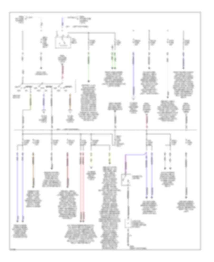
POWER DISTRIBUTION
Power Distribution Wiring Diagram (1 of 2) for Toyota Supra 1995

List of elements for Power Distribution Wiring Diagram (1 of 2) for Toyota Supra 1995:
- (can)
- (left side of engine compt)
- (usa)
- (usa) (canada)
- A/c condenser fan motor, radiator fan motor, radiator fan relay 1, radiator fan relay 2
- Abs & traction ecu, traction pump & motor, traction motor relay
- Abs 1 fuse 60a
- Abs 2 fuse 30a (turbo only)
- Abs actuator, abs relay, abs ecu, abs & traction ecu, traction brake actuator, abs motor relay, abs solenoid relay, traction solenoid relay
- Alt fuse 120a
- Alt-s fuse 7.5a
- Am1 fuse 50a 60a
- Am2 fuse 30a
- Auto antenna control relay, auto antenna motor, radio & player, stereo power amplifier
- Battery
- Blower motor control relay, heater relay
- Clock, main daytime running light relay, interior light diode, left door courtesy switch, right door courtesy switch, door key lock/unlock switch, ignition key cylinder light, luggage compartment light switch, luggage compartment light, personal light, open door warning light, theft deterrent & door lock control ecu, power main relay, integration relay
- Combination meter, horn switch, turn signals, horns, hazard switch, theft deterrent horn, theft deterrent & door lock control ecu, turn signal flasher, horn relay
- Data link connector 1, electronic transmission control solenoid, engine control module, fuel pump ecu, main heated oxygen sensor, sub heated oxygen sensor, idle air control valve, mass air flow meter, front main heated oxygen sensor, rear main heated oxygen sensor, vsv's, efi main relay, efi 2 relay
- Dimmer relay
- Dimmer switch, fog light switch, left hi & low beam headlights, fog light relay
- Dimmer switch, fog light switch, left low beam headlight, fog light relay
- Dimmer switch, left hi beam headlight, combination meter
- Dimmer switch, right hi & low beam headlights, combination meter
- Dimmer switch, right hi beam headlight, combination meter
- Dimmer switch, right low beam headlight
- Diode, engine control module, outside rearview mirrors
- Dome fuse 7.5a
- Drl fuse 7.5a
- Drl relay 3
- E20 (non- turbo) (engine harness, forward of r/b 2)
- E7 (engine harness, (forward of relay block 2)
- E7 (or e8) (engine harness, (forward of relay block 2)
- E7 (turbo) e20 (non- turbo) (engine harness, forward of r/b 2)
- Efi 1 fuse 30a
- Efi 2 fuse 30a (turbo only)
- Fan fuse 30a (turbo only)
- Fog fuse 15a
- Fog light relay, front fog/parking lights
- From alt c fuse (diagram 1 of 2)
- From am2 fuse (diagram 1 of 2)
- From defog fuse (diagram 2 of 2)
- From gauge fuse (diagram 2 of 2)
- Fuel pump ecu, efi relay 2
- Generator
- Haz- horn fuse 15a
- Head- light relay
- Htr fuse 50a
- J/b 1 (left kick panel)
- Left head fuse 15a
- Left lower head fuse 15a
- Left upper head fuse 15a
- Main fuse 50a
- Mir-htr fuse 10a
- Power fuse 60a
- R/b 4 (left kick panel)
- Rad 1 fuse 20a
- Rear window defogger relay
- Red
- Relay block 2
- Relay block 2 (left side of engine compt)
- Right head fuse 15a
- Right lower head fuse 15a
- Right upper head fuse 15a
- Starter
- Starter relay
- To abs 1 fuse (diagram 1 of 2)
- To ignition switch (diagram 2 of 2)
- To obd-ii fuse (diagram 2 of 2)
- To tail- light relay (diagram 2 of 2)
- To trac fuse (diagram 1 of 2)
- Trac fuse 7.5a (turbo only)
- Traction ecu
Power Distribution Wiring Diagram (2 of 2) for Toyota Supra 1995
List of elements for Power Distribution Wiring Diagram (2 of 2) for Toyota Supra 1995:
- (diagram 1 of 2)
- (left kick panel)
- A/c amplifier, abs ecu, abs & traction ecu, center airbag sensor assembly, cruise control ecu, main daytime running light relay, data link connector 1, right telltail light, traction ecu
- A/c amplifier, center airbag sensor assembly, clock, shift lock ecu, theft deterrent & door lock ecu
- A/c triple pressure switch, a/c amplifier, a/c magnetic clutch & lock sensor, air inlet control servo motor, engine coolant temperature switch, engine control module, heater control switch, radiator fan relay 1, radiator fan relay 2, a/c magnetic clutch relay, heater relay
- Abs actuator, abs relay, a/c amplifier, abs ecu, abs & traction ecu, brake fluid level warning switch, back- up light switch, combination meter, cruise control clutch switch, cruise control ecu, data link connector 1 & 2, main daytime running light relay, engine coolant temp sender, engine oil level sensor, engine control module, fuel pump & sender, generator, light failure sensor, o/d main switch, oil pressure switch, parking brake switch, park/neutral position switch, back-up lights, traction brake actuator, telltale lights, traction ecu, vehicle speed sensor 1, diode, integration relay, rear window degogger relay, abs solenoid relay, traction motor relay, traction solenoid relay
- Abs ecu, abs & traction ecu, abs lateral acceleration sensor, auto antenna control relay, buckle switches, cruise control ecu, pps ecu, shift lock ecu, theft deterrent & door lock control ecu, traction ecu, tension reducer solenoids, power main relay
- Abs ecu, abs & traction ecu, cruise control ecu, engine control module, high mounted stop light, light failure sensor, stop light switch, shift lock ecu, rear combination lights, traction ecu
- Acc
- Ashtray illum, idle-up diode, electronically controlled transmission pattern select switch, engine control module, glove box light, glove box light switch, hazard switch, heater control switch, o/d main switch, rheostat, radio & player, seat heater switch, right tell- tale light, trac off switch
- Auto antenna control relay, radio & player, outside mirrors, stereo power amplifier, integration relay
- C10
- C16
- Center airbag sensor assembly, engine control module, generator, right telltale light
- Cig fuse 15a
- Cigarette lighter
- Combination meter, turn signal switch, front turn signal lights, rear combination lights, hazard switch, turn signal flasher
- Data link connector 3
- Defog fuse 30a
- Door fuse 30a
- E10
- E12
- E17
- Ecu-b fuse 10a
- Ecu-ig fuse 10a
- Engine control module, clutch start switch, park/neutral position switch, theft deterrent & door lock control ecu, starter relay
- From am1 fuse d
- From am2 fuse (diagram 1 of 2)
- From ignition switch (diagram 2 of 2)
- From power fuse (diagram 1 of 2)
- Front & rear wiper/washer switches, front wiper motor, rear wiper motor & relay, washer motor
- Front side marker lights, front fog/ parking lights, license plate light, light failure sensor, rear side marker lights, rear combination lights, diode
- G203 (right kick panel)
- Gauge fuse 10a
- H12
- H15
- Htr fuse 7.5a
- I10
- I14
- Ign fuse 7.5a
- Ignition switch
- J/b 1
- Junction connector 1 (upper center of dash)
- Obd-ii fuse 7.5a (non- turbo only)
- Off
- Panel fuse 10a
- Rad 2 fuse 7.5a
- Right power window control switch, left power window & door lock master control switch, left power window motor, right power window motor, power seat control switch, power seat motor, theft deterrent & door lock control ecu, power main relay
- Seat heater switch, seat heaters, seat heater relays
- Seat- htr fuse 15a (canada only)
- Start
- Start fuse 7.5a
- Stop fuse 15a
- Tail fuse 10a
- Tail- light relay
- To cig fuse (diagram 2 of 2)
- To ign fuse (diagram 2 of 2)
- To rear defogger relay (diagram 1 of 2)
- To rear window defogger relay (diagram 2 of 2)
- Turn fuse 7.5a
- Wiper fuse 20a