POWER DISTRIBUTION
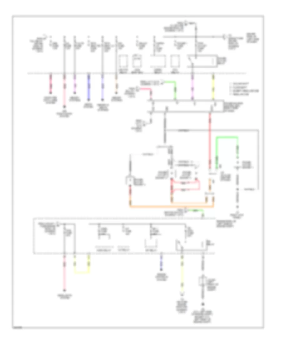
Power Distribution Wiring Diagram (1 of 3) for Toyota Tundra Limited 2010

List of elements for Power Distribution Wiring Diagram (1 of 3) for Toyota Tundra Limited 2010:
- (floor shift: left kick panel) (column shift: left side of dash) j1
- (left side of dash) driver side j/b
- (left side of engine compt) engine room j/b
- (left side of engine compt) engine room r/b
- 4.0l
- 4wd fuse 20a
- A/c ig fuse 10a
- A/pump fuse 50a
- Acc
- Acc cut relay (right side of dash)
- Acc fuse 7.5a
- Acc relay
- Air conditioning system
- Alt fuse 180a 140a
- Alt s fuse 5a
- Am1 fuse 7.5a
- Am2 fuse 7.5a
- Amp fuse 30a
- Anti-lock brakes & electronic power steering systems
- Anti-theft system
- B10
- B13
- B17
- Battery
- Becc
- Bk/up lp fuse 10a
- C10
- C11
- C22
- Cig fuse 15a
- Cigarette lighter
- D14
- D24
- D43
- D45
- D47
- D55
- D56
- D57
- D62
- D63
- D65
- D66
- Dome fuse 7.5a
- Door locks, mirrors, exterior lights, cruise control, sound & navigation systems
- E10
- Ecu b1 fuse 7.5a
- Ecu ig 1 fuse 7.5a
- Ecu ig 2 fuse 7.5a
- Electronic power steering system
- Engine controls system
- Except 4.0l
- Exterior lights & anti-lock brakes systems
- Exterior lights system
- Gnd1
- Headlights & exterior lights systems
- Htr fuse 50a
- Ig1 1 relay
- Ig1 2 relay
- Ig1 3 relay
- Ignition switch
- Instrument cluster, anti-theft, door locks & interior lights systems
- Interior lights & navigation systems
- Interior lights system
- J/c j71 & j72 (left side of dash)
- J/c j72 j71 & j72 (left side of dash)
- J/c j73 & j74 (left side of dash)
- J/c j73 & j74 (left side of dash) j73
- J71
- J72
- J73
- J74
- Lh ig fuse 7.5a
- Lh j/b fuse 150a
- Lock
- Main body ecu
- Memory systems
- Memory, mirrors, defogger, warning, anti-theft, air conditioning, navigation, power tops, shift interlock, exterior lights, electronic power steering, instrument cluster & anti-lock brakes systems
- Mirrors system
- Off
- Panel fuse 7.5a
- Pnk
- Rad 1 fuse 15a
- Red
- Seat htr fuse 20a
- Seats system
- Seats, headlights, navigation, defogger, transmissions, exterior lights, cruise control, mirrors, engine controls & sound systems
- Shift interlock system
- Short pin
- Sound & navigation systems
- Sound, navigation & instrument cluster systems
- St fuse 30a
- Start
- Starting/ charging & defogger systems
- Starting/ charging system
- Tail fuse 15a
- Tail relay
- To ig2 relay engine room j/b (diagram 2 of 3)
- To inverter relay (diagram 3 of 3)
- To main fuse engine room j/b (diagram 2 of 3)
- To met b fuse engine room r/b (diagram 3 of 3)
- To obd fuse driver side j/b (diagram 2 of 3)
- To power outlet fuse driver side j/b (diagram 2 of 3)
- To power source control ecu (diagram 2 of 3)
- To stop fuse engine room r/b (diagram 3 of 3)
- Tow bk/up fuse 7.5a
- Transmissions system
- Transmissions, exterior lights & navigation systems
- Trly
- Turn haz fuse 15a
- Wiper fuse 30a
- Wiper/washer system
- Wsh fuse 20a
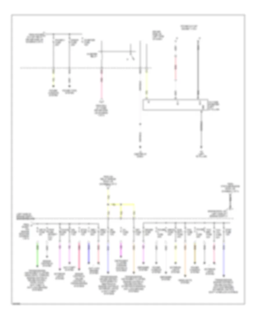
Power Distribution Wiring Diagram (2 of 3) for Toyota Tundra Limited 2010
List of elements for Power Distribution Wiring Diagram (2 of 3) for Toyota Tundra Limited 2010:
- +b1
- A/c fuse 7.5a
- A/f fuse 15a
- A/f relay
- A2 (5.7l: left side of engine compt) (except 5.7l: left front of engine compt)
- Air conditioning system
- Altb
- Cargo lp fuse 7.5a
- Cargo relay
- Column shift
- Computer data lines system
- D18
- D34
- D36
- D54
- D58
- D60
- D61
- Dr/lck fuse 25a
- Driver side j/b (left side of dash)
- Efi 1 fuse 25a
- Efi relay
- Engine controls system
- Engine room j/b (left side of engine compt)
- Except regular cab
- Floor shift
- Fr p/ seat lh fuse 30a
- Fr p/ seat rh fuse 30a
- From a/pump 1 fuse engine room j/b (diagram 1 of 3)
- From e
- From ecu ig 1 (diagram 1 of 3)
- From ignition switch (diagram 1 of 3)
- From j/c 71 & 72 (diagram 1 of 3)
- From lh j/b fuse engine room j/b (diagram 1 of 3)
- Gnd
- Headlights system
- Horn fuse 10a
- Horn relay
- Ig2 main fuse 30a
- Ig2 relay
- J/c a44 (left front of engine compt)
- J/c j81 & j82 (center of dash)
- J3 (right kick panel)
- J81
- J82
- Main body ecu
- Main fuse 40a
- Memory & seats systems
- Memory systems
- Mir fuse 15a
- Mir htr relay
- Obd fuse 7.5a
- Out1
- P/w relay
- Pnk
- Power 1 fuse 30a
- Power outlet relay
- Power outlet socket 1
- Power outlet socket 2
- Power outlet socket 3
- Power source control ecu (right side of dash)
- Pwr outlet fuse 15a
- Red
- Regular cab
- Rlc
- Seats system
- Tail relay driver side j/b (diagram 1 of 3)
- Ti & te fuse 15a
- To ign fuse engine room r/b (diagram 3 of 3)
- To s/roof fuse driver side j/b (diagram 3 of 3)
- Vac
- Vig
Power Distribution Wiring Diagram (3 of 3) for Toyota Tundra Limited 2010
List of elements for Power Distribution Wiring Diagram (3 of 3) for Toyota Tundra Limited 2010:
- (left side of engine compt) engine room r/b
- Abs 1 fuse 50a
- Abs 2 fuse 40a
- Ac1
- Ac2
- Anti-lock brakes system
- Anti-theft system
- D35
- D37
- D62
- D64
- Defog fuse 40a
- Defogger system
- Deicer fuse 20a
- Driver side j/b (left side of dash)
- Engine controls system
- Engine controls, cruise control & transmissions systems
- Engine room j/b (left side of engine compt)
- Etcs fuse 10a
- Exterior lights system
- F/pmp fuse (except 4.0l) 15a
- Fog fuse 15a
- From c short pin engine room r/b (diagram 1 of 3)
- From ecu ig 1 fuse driver side j/b (diagram 1 of 3)
- From htr fuse engine room j/b (diagram 1 of 3)
- From ig2 relay engine room j/b (diagram 2 of 3)
- From power l outlet relay driver side j/b (diagram 2 of 3)
- Gnd
- Headlights system
- Ign fuse 10a
- Imb fuse 7.5a
- Inj fuse 10a
- Instrument cluster & engine controls systems
- Inverter fuse 15a
- Inverter relay
- J2 (center of dash)
- Met b fuse 5a
- Met fuse 7.5a
- P2 (left "b" pillar)
- Pnk
- Power 3 fuse 20a
- Power fuse 25a
- Power fuse 30a
- Power outlet socket (115v)
- Power tops system
- Power windows system
- Red
- S/roof fuse 25a
- Stop fuse 15a
- Sub batt fuse 40a
- Tow brk fuse 30a
- Tow tail fuse 30a
- Towing fuse 30a
- Transmissions, engine controls, cruise control, anti-lock brakes, exterior lights & shift interlock systems
- Transmissions, instrument cluster, engine controls, cruise control, starting/charging & anti-lock brakes systems
- Transmissions, instrument cluster, headlights, warning, engine controls, cruise control, door locks, anti-theft & anti-lock brakes systems
- Voltage inverter (left "c" pillar)