POWER DISTRIBUTION
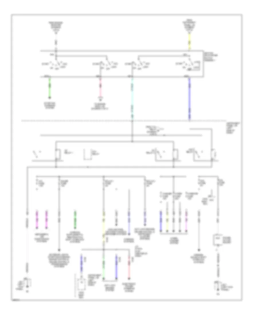
Power Distribution Wiring Diagram (1 of 3) for Toyota Yaris L 2013

List of elements for Power Distribution Wiring Diagram (1 of 3) for Toyota Yaris L 2013:
- A77
- A78
- Abs 1 fuse 50a
- Abs 2 fuse 30a
- Ad8
- Air conditioning system
- Alt fuse 120a
- Alt-s fuse 7.5a
- Am2 fuse 7.5a
- Anti-lock brakes system
- Anti-lock brakes, interior lights & sound systems
- Anti-theft system
- Battery
- Bcyl
- Becu
- C21
- Cooling fans & air conditioning systems
- Dcc fuse 30a
- Def fuse 30a
- Defogger system
- Dome fuse 15a
- Ecu-b 1 fuse 5a
- Ecu-b 2 fuse 5a
- Electronic power steering system
- Engine controls, transmissions & cruise control systems
- Engine room j/b (left side of engine compt)
- Engine room j/b 2
- Engine room r/b (left side of engine compt)
- Engine room r/b 2 (right side of engine compt)
- Eps fuse 50a
- Etcs fuse 10a
- Exterior lights & instrument cluster systems
- From engine room j/b (diagram 1 of 3)
- Fusible link block (left rear of engine compt)
- Generator
- H-lp main fuse 7.5a
- Haz fuse 15a
- Headlights system
- Htr fuse 40a
- Instrument panel j/b (left side of dash)
- Main body ecu
- Main fuse 80a
- Ptc fuse 80a
- R/i fuse 50a
- Rdi fan fuse 30a
- Red
- S-horn fuse 10a
- St fuse 30a
- Starting/ charging system
- To engine room j/b (diagram 3 of 3)
- To engine room j/b 2 (diagram 1 of 3)
- To ignition or starter switch assembly (diagram 2 of 3)
- To instrument panel j/b (diagram 3 of 3)
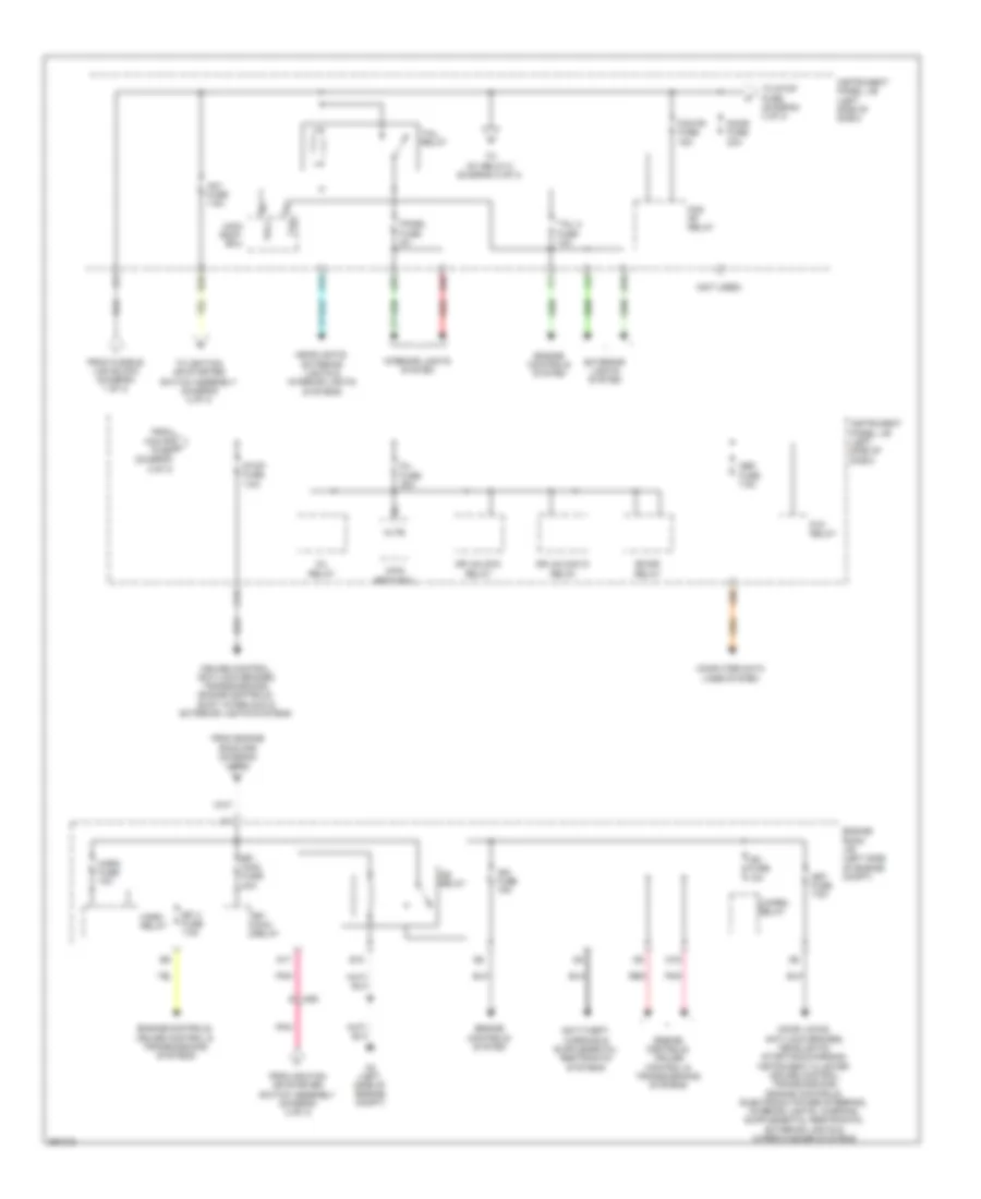
Power Distribution Wiring Diagram (2 of 3) for Toyota Yaris L 2013
List of elements for Power Distribution Wiring Diagram (2 of 3) for Toyota Yaris L 2013:
- A/c fuse 7.5a
- A11
- A29
- A40
- A49
- A51
- A54
- Acc
- Acc fuse 5a
- Acc relay
- Am1
- Am2
- Anti-lock brakes system
- Anti-lock brakes, cruise control & instrument cluster systems
- B13
- B37
- C14
- C15
- C27
- C32
- Cig fuse 15a
- Cooling fans, air conditioning & defogger systems
- D148
- D149
- D16
- D32
- Defogger & air conditioning systems
- Ecu-ig 1 fuse 5a
- Ecu-ig 2 fuse 5a
- Electronic power steering system
- Exterior lights, starting/charging, engine controls, cruise control & transmissions systems
- From engine room r/b (diagram 1 of 3)
- From instrument panel j/b (diagram 3 of 3)
- From tail relay g (diagram 3 of 3)
- Gauge fuse 10a
- Ig1
- Ig1 relay 1
- Ig1 relay 2
- Ig2
- Ignition or starter switch assembly
- Instrument panel j/b (left side of dash)
- J/b 7 (left kick panel)
- J/c d148 & d149 (center of dash)
- Lock
- Main body ecu
- Mirrors, sound & shift interlock systems
- Off
- On off
- P/w relay
- Pnk
- Power outlet socket
- Red
- St2
- Start
- Starting/ charging system
- To engine room j/b (diagram 3 of 3)
- Warning systems
- Washer fuse 15a
- Wiper fuse 20a
- Wiper rr fuse 15a
- Wiper/ washer system
Power Distribution Wiring Diagram (3 of 3) for Toyota Yaris L 2013
List of elements for Power Distribution Wiring Diagram (3 of 3) for Toyota Yaris L 2013:
- (not used)
- A19
- A2 (left side of engine compt)
- A35
- A50
- A56
- Ad8
- Altb
- Am1 fuse 7.5a
- B40
- Bk/dr relay
- C/open relay
- C12
- Computer data lines system
- Cruise control, anti-lock brakes, transmissions, engine controls, shift interlock & exterior lights systems
- D/l fuse 25a
- D/l relay
- D10
- D17
- D19
- Door fuse 20a
- Dr unlock d relay
- Dr unlock relay
- E10
- Efi 3 fuse 7.5a
- Efi main fuse 20a
- Efi main relay
- Engine controls system
- Engine controls, cruise control & transmissions systems
- Engine room j/b (left side of engine compt)
- Exterior lights system
- Fog fr fuse 15a
- Fog fr relay
- From engine room r/b (diagram 1 of 3)
- From fog fr h fuse (diagram 3 of 3)
- From fusible link block (diagram 1 of 3)
- From ignition or starter switch assembly (diagram 2 of 3)
- Headlights, exterior lights & interior lights systems
- Horn fuse 10a
- Horn relay
- Ig2 fuse 10a
- Ig2 relay
- Ign fuse 15a
- Instrument panel j/b (left side of dash)
- Interior lights system
- Main body ecu
- Met fuse 7.5a
- Obd fuse 7.5a
- P/w relay
- Panel fuse 5a
- Pnk
- Red
- Stop fuse 7.5a
- Tail 2 fuse 10a
- Tail relay
- Tlh
- To ig1 relay 2 (diagram 2 of 3)
- To ignition or starter switch assembly (diagram 2 of 3)
- To stop fuse (diagram 3 of 3)
- Trly