POWER DISTRIBUTION
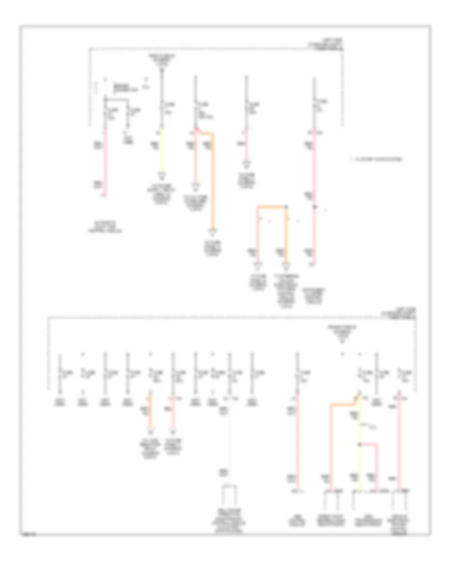
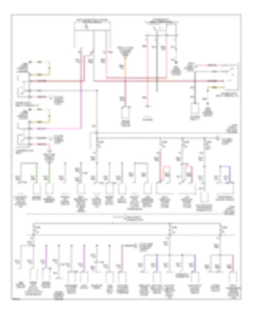
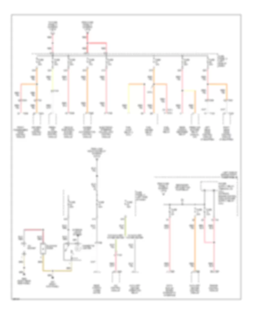
Power Distribution Wiring Diagram, Early Production (1 of 6) for Volkswagen Golf 2010

List of elements for Power Distribution Wiring Diagram, Early Production (1 of 6) for Volkswagen Golf 2010:
- (not used)
- Abs control module
- Amplifier
- Battery
- Battery monitoring control module (w/ start/ stop system)
- Brake light switch (w/ dsg transmission)
- Coolant fan control module
- Data bus on board diagnostic interface
- Dual tone horn relay
- From fuse 3 (diagram 1 of 6)
- From fuse 5 (diagram 1 of 6)
- Fuse
- Fuse 150a 200a
- Fuse 30a
- Fuse 40a
- Fuse 50a
- Fuse 5a
- Fuse 80a
- Fuse panel a
- Fuse panel b
- G1 (battery to body)
- Generator
- Nca
- Power steering control module
- Red
- Starter
- T2a
- T2c
- T38
- T40
- T4x
- T52a
- T52c
- To battery monitoring control module (diagram 1 of 6)
- To fuse 12 (diagram 4 of 6)
- To fuse 19 (diagram 2 of 6)
- To fuse 25 (diagram 1 of 6)
- To fuse 3 (diagram 2 of 6)
- To fuse panel c (diagram 4 of 6)
- Vehicle electrical system control module
- W/ 140a generator
- W/ 90a/120a generator
- Wiper motor control module
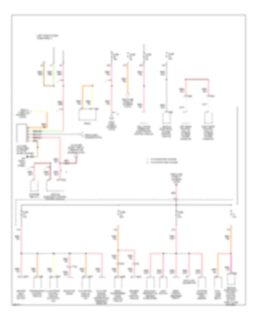
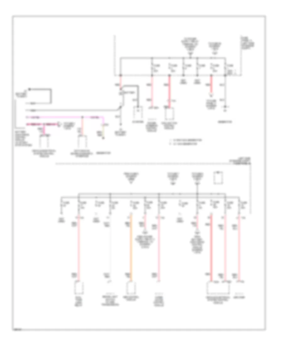
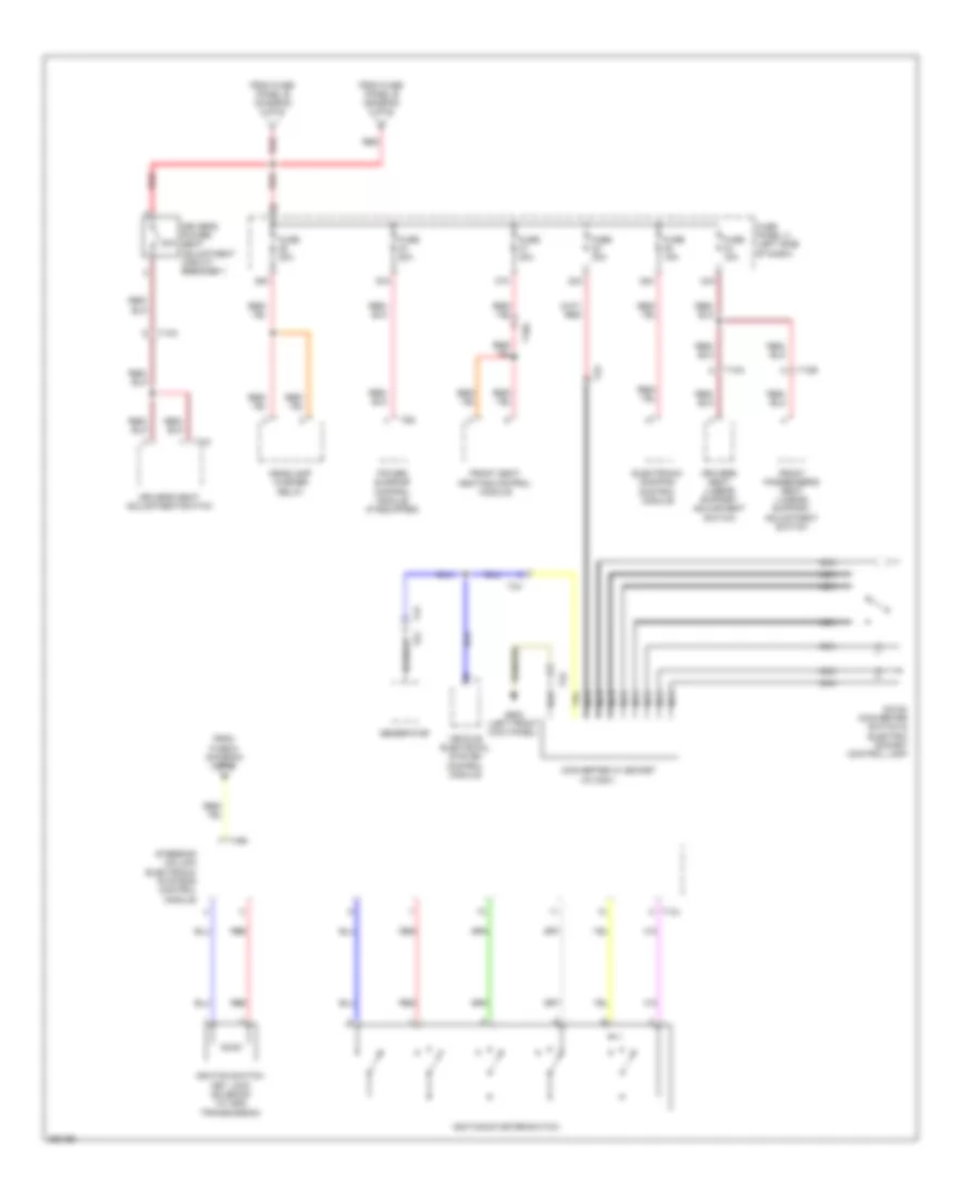
Power Distribution Wiring Diagram, Early Production (2 of 6) for Volkswagen Golf 2010
List of elements for Power Distribution Wiring Diagram, Early Production (2 of 6) for Volkswagen Golf 2010:
- (left side of engine compt) fuse panel b
- (not used)
- 2.0l
- Abs control module
- Automatic glow time control module
- Bridge connector
- Cell phone operating electronics control module (w/o start/ stop system)
- Direct shift gearbox (dsg) mechatronic
- Dsg transmission mechatronic
- From fuse 25 (diagram 1 of 6)
- Frome fuse 25 (diagram 1 of 6)
- Fuse
- Fuse 15a
- Fuse 25a (or 15a)
- Fuse 30a
- Fuse 40a
- Fuse 50a
- Fuse 5a
- Instrument cluster control module
- Red
- T20e
- T40
- T52a
- To fuse panel b (diagram 3 of 6)
- To fuse panel c (diagram 3 of 6)
- To fuse panel c (diagram 5 of 6)
- To load reduction relay (diagram 6 of 6)
- To steering column electronic systems control module (diagram 5 of 6)
- To voltage stabilizer (diagram 3 of 6)
- Vehicle electrical system control module
- W/ start/ stop system
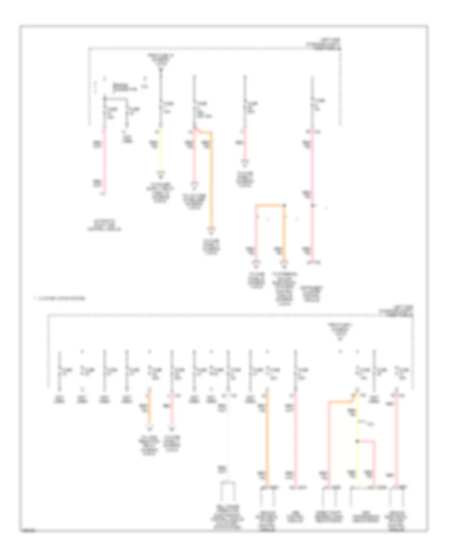
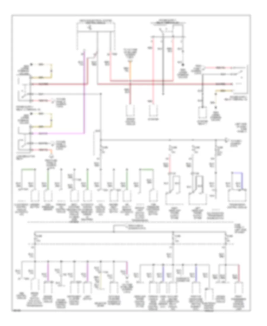
Power Distribution Wiring Diagram, Early Production (3 of 6) for Volkswagen Golf 2010
List of elements for Power Distribution Wiring Diagram, Early Production (3 of 6) for Volkswagen Golf 2010:
- (left side of dash) fuse panel c
- 10a
- 12a
- 13a
- 14a
- 15a
- 17a
- 28a
- 47a
- 48a
- A/c control module (manual a/c)
- Auxiliary engine coolant heater radio frequency receiver
- Cell phone operating electronics control module
- Climatronic control module (automatic a/c)
- Compass magnetic field sensor
- Data link connector
- Driver's door control module
- Dual tone horn relay
- From fuse 2 (diagram 6 of 6)
- From fuse 8 (diagram 2 of 6)
- From fuse 8 h (diagram 2 of 6)
- From fuse panel b (diagram 2 of 6)
- From fuse panel c (diagram 3 of 6)
- Front passenger's door control module
- Fuse 10a
- Fuse 15a
- Fuse 20a
- Fuse 5a
- G47 (right kick panel)
- Heater/ heat output switch
- Left rear control module (w/ rear power windows)
- Light switch
- Radio
- Rain/light recognition sensor (if equipped)
- Rear window defogger relay
- Red
- Right rear control module (w/ rear power windows)
- Selector lever
- Starter relay 2
- T10s
- T16b
- T20a
- T20b
- T20c
- T28
- T28a
- T28b
- T28c
- T52
- T52b
- T52c
- Transmission control module
- Vehicle electrical system control module
- Vehicle electrical system control module (w/ anti theft alarm system)
- Voltage stabilizer (w/ stop/ start system)
- W/ stop/start system
- W/o stop/start system
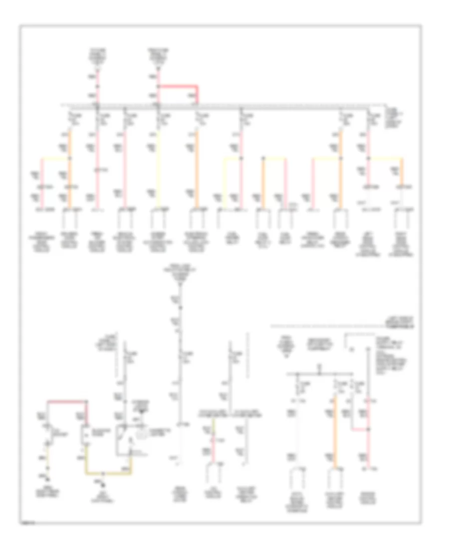
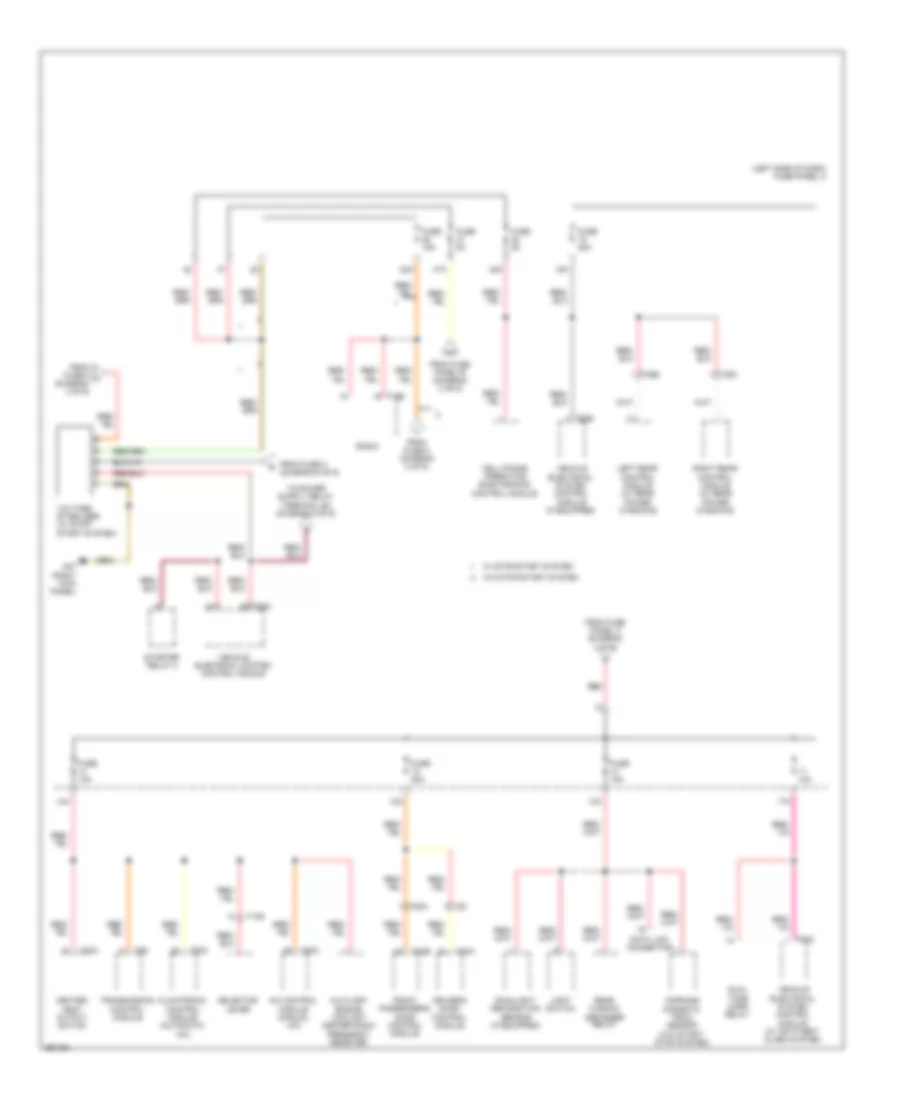
Power Distribution Wiring Diagram, Early Production (4 of 6) for Volkswagen Golf 2010
List of elements for Power Distribution Wiring Diagram, Early Production (4 of 6) for Volkswagen Golf 2010:
- (2.0l)
- (2.5l)
- (left side of engine compt) fuse panel b
- (terminal 30)
- 12v socket
- 20a
- 21a
- 22a
- 23a
- 24a
- 25a
- 26a
- 27a
- 40a
- 41a
- 42a
- A/c control module
- Access start authorization control module
- Auxiliary heater control module
- Auxiliary heater operation relay
- Blocking diode
- Cigarette lighter
- Data bus on board diagnostic interface
- Driver's door control module
- Electronic steering column lock control module
- Engine control module
- Fresh air blower control module
- Fresh air blower relay (manual a/c)
- From fuse 6 (diagram 1 of 6)
- From fuse panel a (diagram 1 of 6)
- From load induction relay (diagram 6 of 6)
- Front passenger's door control module
- Fuel primer relay
- Fuel pump relay
- Fuel pump relay 2 (2.0l)
- Fuse 10a
- Fuse 15a
- Fuse 20a
- Fuse 25a
- Fuse 30a
- Fuse 40a
- Fuse 5a
- Fuse panel c (left side of dash)
- G47 (right kick panel)
- G682 (right rear side panel)
- Interior lights system
- Left rear door control module (if equipped)
- Rear window defogger relay
- Rear window wiper motor
- Red
- Right rear door control module (if equipped)
- Secondary air injection pump relay
- T10k
- T16s
- T18c
- T18d
- T20a
- T20b
- T28
- T28a
- T28b
- T28c
- T2g
- T2o
- T32b
- T40
- T52b
- T5d
- T5e
- T94
- To fuse panel c (diagram 3 of 6)
- Vehicle electrical system control module
- W/ auxiliary water heater
- W/o auxiliary water heater
Power Distribution Wiring Diagram, Early Production (5 of 6) for Volkswagen Golf 2010
List of elements for Power Distribution Wiring Diagram, Early Production (5 of 6) for Volkswagen Golf 2010:
- 20a
- 32a
- 33a
- 34a
- 35a
- 36a
- 37a
- Converter w/ socket 12v-230v
- Dc/ac converter switch & electric socket control lamp
- Driver's power seat adjustment circuit breaker 1
- Driver's seat adjustment switch
- Driver's seat lumbar support adjustment switch
- Electronic damping control module
- From fuse 6 (diagram 2 of 6)
- From fuse panel b (diagram 2 of 6)
- Front passenger's seat lumbar support adjustment switch
- Front seat heating control module
- Fuse 15a
- Fuse 20a
- Fuse 30a
- Fuse panel c (left side of dash)
- G602 (left front kick panel)
- Generator
- Headlamp washer relay
- Ignition switch key lock solenoid (w/ dsg transmission)
- Ignition/starter switch
- Nca
- Power sunroof control module (if equipped)
- Red
- Steering column electronic systems control module
- T10a
- T10b
- T12j
- T20d
- T2c
- T3x
- T4t
- T4w
- T6c
- Vehicle electrical system control module
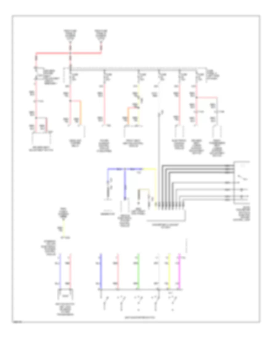
Power Distribution Wiring Diagram, Early Production (6 of 6) for Volkswagen Golf 2010
List of elements for Power Distribution Wiring Diagram, Early Production (6 of 6) for Volkswagen Golf 2010:
- 30a
- A/c control module (manual a/c)
- Abs control module
- Air bag control module
- Air quality sensor
- Asr/esp button
- Auxiliary heater operation relay (manual a/c)
- Backup light switch (w/ dual clutch transmission)
- Brake light switch (2.5l & 2.0l w/ dual clutch transmission)
- Climatronic control module (automatic a/c)
- Data bus on board diagnostic interface
- Diagnostic connector
- Distance regulation control module
- Electronic damping control module
- Engine control module
- From fuse 30 (diagram 6 of 6)
- From fuse 7 g (diagram 2 of 6)
- From fuse panel b (diagram 2 of 6)
- From voltage stabilizer (diagram 3 of 6)
- Front passenger's air bag disabled indicator lamp
- Fuel pump relay (2.5l)
- Fuse (2.0l) 20a
- Fuse 10a
- Fuse 5a
- Fuse panel c (left side of dash)
- G605 (upper steering column)
- Headlamp range control module (w/ hid)
- Heater/ heat output switch
- High pressure sensor
- Instrument cluster control module
- Left headlamp power output stage
- Light switch
- Load reduction relay
- Multifunction transmission range switch
- Nca
- Parking aid control module
- Power steering control module
- Red
- Right headlamp power output stage
- Seat recognition control module (w/ rear side airbag)
- Selector lever
- Starter
- Starter relay 1
- T10s
- T14e
- T20c
- T32a
- T52
- T52b
- T6z
- T94
- Tire pressure monitoring display button
- To fuse 2 (diagram 6 of 6)
- To fuse panel b (diagram 1 of 6)
- To fuse panel c (diagram 4 of 6)
- To voltage stabilizer (diagram 3 of 6)
- Transmission control module
- Vehicle electrical system control module
Power Distribution Wiring Diagram, Late Production (1 of 6) for Volkswagen Golf 2010
List of elements for Power Distribution Wiring Diagram, Late Production (1 of 6) for Volkswagen Golf 2010:
- (left side of engine compt) fuse panel b
- (not used)
- Abs control module
- Amplifier
- Battery
- Battery monitoring control module (w/ start/ stop system)
- Brake light switch (w/ dsg transmission)
- Coolant fan control module
- Data bus on board diagnostic interface
- Dual tone horn relay
- From battery monitoring control module (diagram 1 of 6)
- From fuse 5 (diagram 1 of 6)
- Fuse
- Fuse 150a 200a
- Fuse 15a
- Fuse 30a
- Fuse 40a
- Fuse 50a
- Fuse 5a
- Fuse 80a
- Fuse panel a (left side of engine compt)
- G1 (battery to body)
- Generator
- Nca
- Power steering control module
- Red
- Starter
- T2a
- T2c
- T38
- T40
- T4x
- T52a
- T52c
- To fuse 25 (diagram 1 of 6)
- To fuse 3 (diagram 1 of 6)
- To fuse 5 (diagram 2 of 6)
- To fuse 7 (diagram 2 of 6)
- To fuse panel c (diagram 4 of 6)
- Vehicle electrical system control module
- W/ 140a generator
- W/ 90a/120a generator
- Wiper motor control module
Power Distribution Wiring Diagram, Late Production (2 of 6) for Volkswagen Golf 2010
List of elements for Power Distribution Wiring Diagram, Late Production (2 of 6) for Volkswagen Golf 2010:
- (left side of engine compt) fuse panel b
- (not used)
- 2.0l
- Abs control module
- Automatic glow time control module
- Bridge connector
- Cell phone operating electronics control module (w/o start/ stop system)
- Direct shift gearbox (dsg) mechatronic
- Dsg transmission mechatronic
- From fuse 19 (diagram 1 of 6)
- From fuse 3 (diagram 1 of 6)
- Fuse
- Fuse 15a
- Fuse 20a
- Fuse 25a (or 15a)
- Fuse 30a
- Fuse 40a
- Fuse 50a
- Fuse 5a
- Instrument cluster control module
- Red
- T20e
- T32
- T40
- T47c
- T52a
- T52c
- To fuse panel b (diagram 3 of 6)
- To fuse panel c (diagram 3 of 6)
- To fuse panel c (diagram 5 of 6)
- To load reduction relay (diagram 6 of 6)
- To steering column electronic systems control module (diagram 5 of 6)
- To voltage stabilizer (diagram 3 of 6)
- Vehicle electrical system control module
- W/ start/ stop system
Power Distribution Wiring Diagram, Late Production (3 of 6) for Volkswagen Golf 2010
List of elements for Power Distribution Wiring Diagram, Late Production (3 of 6) for Volkswagen Golf 2010:
- (left side of dash) fuse panel c
- 10a
- 12a
- 13a
- 14a
- 15a
- 17a
- 28a
- 47a
- 48a
- A/c control module (manual a/c)
- Auxiliary engine coolant heater radio frequency receiver
- Cell phone operating electronics control module
- Climatronic control module (automatic a/c)
- Compass magnetic field sensor (w/o start/ stop system)
- Data link connector
- Driver's door control module
- Dual tone horn relay
- From fuse 2 (diagram 6 of 6)
- From fuse 8 (diagram 2 of 6)
- From fuse 8 j (diagram 2 of 6)
- From fuse panel b (diagram 2 of 6)
- From fuse panel c (diagram 4 of 6)
- Front passenger's door control module
- Fuse 10a
- Fuse 15a
- Fuse 20a
- Fuse 5a
- G47 (right kick panel)
- Heater/ heat output switch
- Left rear control module (w/ rear power windows)
- Light switch
- Radio
- Rain/light recognition sensor (if equipped)
- Rear window defogger relay
- Red
- Right rear control module (w/ rear power windows)
- Selector lever
- Starter relay 2
- T10s
- T16b
- T20a
- T20b
- T20c
- T28
- T28a
- T28b
- T28c
- T52
- T52b
- T52c
- Transmission control module
- Vehicle electrical system control module
- Vehicle electrical system control module (if equipped)
- Vehicle electrical system control module (w/ antitheft alarm system)
- Voltage stabilizer (w/ stop/ start system)
- W/ stop/start system
- W/o stop/start system
Power Distribution Wiring Diagram, Late Production (4 of 6) for Volkswagen Golf 2010
List of elements for Power Distribution Wiring Diagram, Late Production (4 of 6) for Volkswagen Golf 2010:
- (2.0l)
- (2.5l)
- (left side of engine compt)
- (terminal 30)
- 12v socket
- 20a
- 21a
- 22a
- 23a
- 24a
- 25a
- 26a
- 27a
- 3a (2.0l)
- 40a
- 41a
- 42a
- A/c control module
- Access start authorization control module
- Auxiliary heater control module
- Auxiliary heater operation relay
- Blocking diode
- Cigarette lighter
- Data bus on board diagnostic interface
- Driver's door control module
- Electronic steering column lock control module
- Engine control module
- Fresh air blower control module
- Fresh air blower relay (manual a/c)
- From fuse panel a (diagram 1 of 6)
- From load induction relay (diagram 6 of 6)
- Front passenger's door control module
- Fuel primer relay (2.0l)
- Fuel pump relay
- Fuel pump relay 2 (2.0l)
- Fuse 10a
- Fuse 15a
- Fuse 20a
- Fuse 25a
- Fuse 30a
- Fuse 40a
- Fuse 5a
- Fuse panel b
- Fuse panel c (left side of dash)
- G47 (right kick panel)
- G682 (right rear side panel)
- Interior lights system
- Left rear door control module (if equipped)
- Rear window defogger relay
- Rear window wiper motor
- Red
- Right rear door control module (if equipped)
- Secondary air injection pump relay
- T10k
- T16s
- T18c
- T18d
- T20a
- T20b
- T28
- T28a
- T28b
- T28c
- T2g
- T2o
- T32b
- T40
- T52b
- T5d
- T5e
- T94
- To fuse panel c (diagram 3 of 6)
- Vehicle electrical system control module
- W/ auxiliary water heater
- W/o auxiliary water heater
Power Distribution Wiring Diagram, Late Production (5 of 6) for Volkswagen Golf 2010
List of elements for Power Distribution Wiring Diagram, Late Production (5 of 6) for Volkswagen Golf 2010:
- 12v-230v
- 20a
- 32a
- 33a
- 34a
- 35a
- 36a
- 37a
- Converter w/ socket
- Dc/ac converter switch & electric socket control lamp
- Driver's power seat adjustment circuit breaker 1
- Driver's seat adjustment switch
- Driver's seat lumbar support adjustment switch
- Electronic damping control module
- From fuse 6 (diagram 2 of 6)
- From fuse panel b (diagram 2 of 6)
- Front passenger's seat lumbar support adjustment switch
- Front seat heating control module
- Fuse 15a
- Fuse 20a
- Fuse 30a
- Fuse panel c (left side of dash)
- G602 (left front kick panel)
- Generator
- Headlamp washer relay
- Ignition switch key lock solenoid (w/ dsg transmission)
- Ignition/starter switch
- Nca
- Power sunroof control module (if equipped)
- Red
- Steering column electronic systems control module
- T10a
- T10b
- T12j
- T16r
- T2c
- T3x
- T4t
- T4w
- T6c
- Vehicle electrical system control module
Power Distribution Wiring Diagram, Late Production (6 of 6) for Volkswagen Golf 2010
List of elements for Power Distribution Wiring Diagram, Late Production (6 of 6) for Volkswagen Golf 2010:
- (left side of dash) fuse panel c
- 30a
- A/c control module (manual a/c)
- Abs control module
- Air bag control module
- Air quality sensor (automatic a/c)
- Asr/esp button
- Automatic dimming interior rearview mirror (if equipped)
- Auxiliary heater operation relay (manual a/c)
- Backup light switch (w/ dual clutch transmission)
- Brake light switch (2.5l & 2.0l dual clutch transmission)
- Climatronic control module (automatic a/c)
- Corning lamps & head range control module
- Data bus on board diagnostic interface
- Diagnostic connector
- Electronic damping control module
- Engine control module
- From fuse 30 (diagram 6 of 6)
- From fuse 7 h (diagram 2 of 6)
- From fuse panel b (diagram 2 of 6)
- Front passenger's air bag disabled indicator lamp
- Fuse (2.0l) 20a
- Fuse 10a
- Fuse 5a
- Fuse panel c (left side of dash)
- G605 (upper steering column)
- Headlamp range control module (w/ hid)
- Heater/ heat output switch
- High pressure sensor
- Instrument cluster control module
- Left headlamp power output stage
- Light switch
- Load reduction relay
- Mass air flow sensor (2.0l)
- Multifunction transmission range switch
- Nca
- Parking aid control module
- Positive crankcase ventilation heating element (2.0l)
- Power steering control module
- Red
- Right headlamp power output stage
- Seat occupied recognition control module (w/ rear side air bag)
- Selector lever
- Starter
- Starter relay 1
- T10s
- T14e
- T14f
- T20c
- T26a
- T32a
- T52
- T52b
- T6z
- T94
- Tire pressure monitoring display button
- To fuse 2 (diagram 6 of 6)
- To fuse panel b (diagram 1 of 6)
- To fuse panel c (diagram 4 of 6)
- To voltage stabilizer (diagram 3 of 6)
- Transmission control module
- Vehicle electrical system control module