POWER DISTRIBUTION
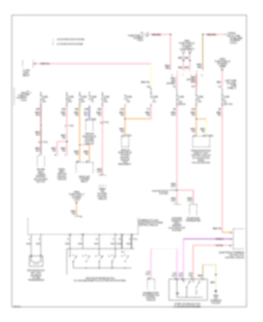
Power Distribution Wiring Diagram (1 of 6) for Volkswagen Jetta Hybrid SEL 2013

List of elements for Power Distribution Wiring Diagram (1 of 6) for Volkswagen Jetta Hybrid SEL 2013:
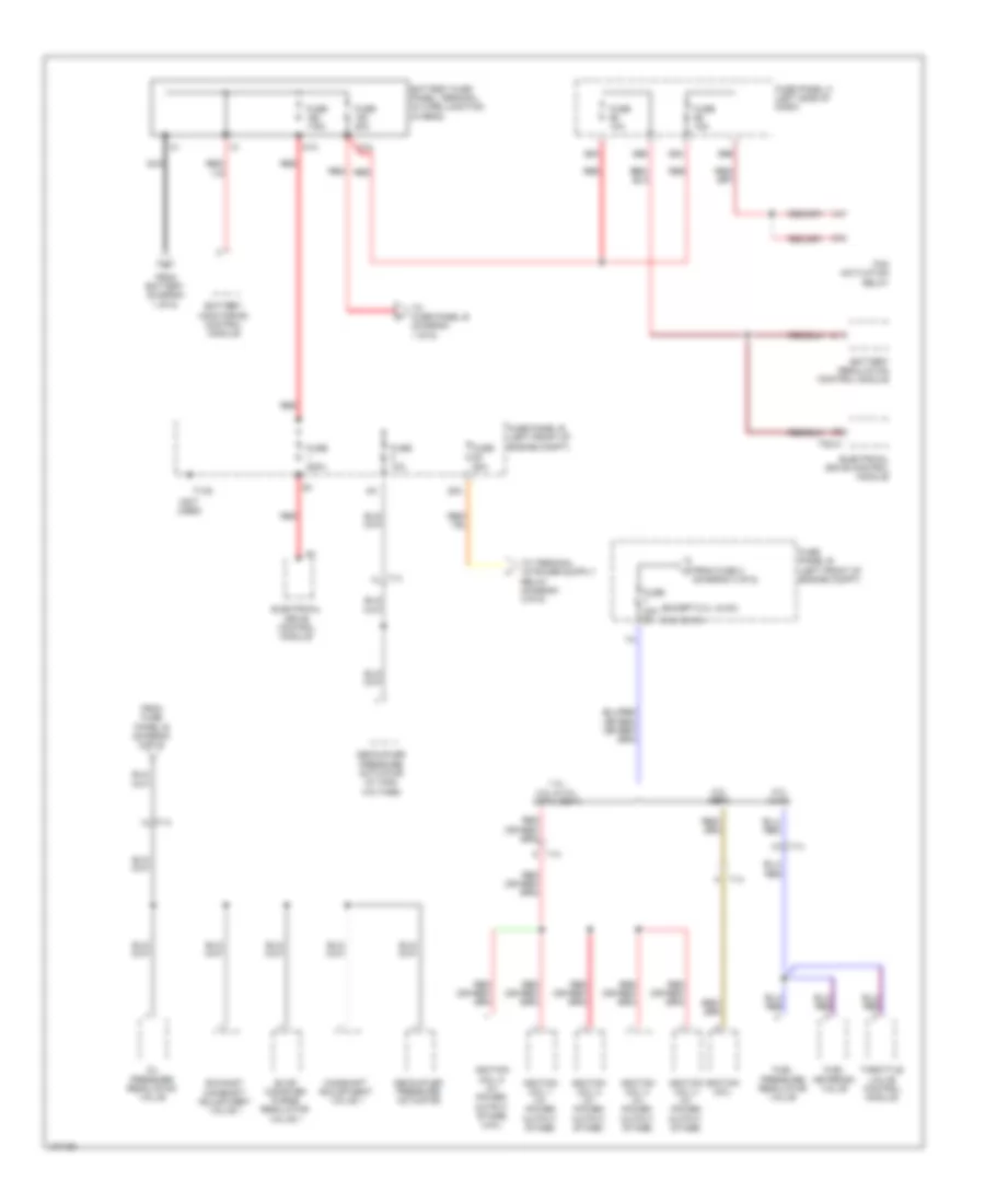
Power Distribution Wiring Diagram (2 of 6) for Volkswagen Jetta Hybrid SEL 2013
List of elements for Power Distribution Wiring Diagram (2 of 6) for Volkswagen Jetta Hybrid SEL 2013:
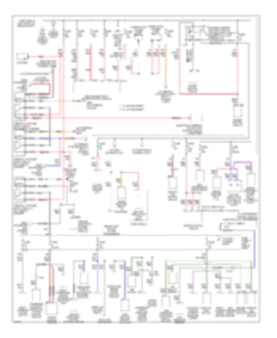
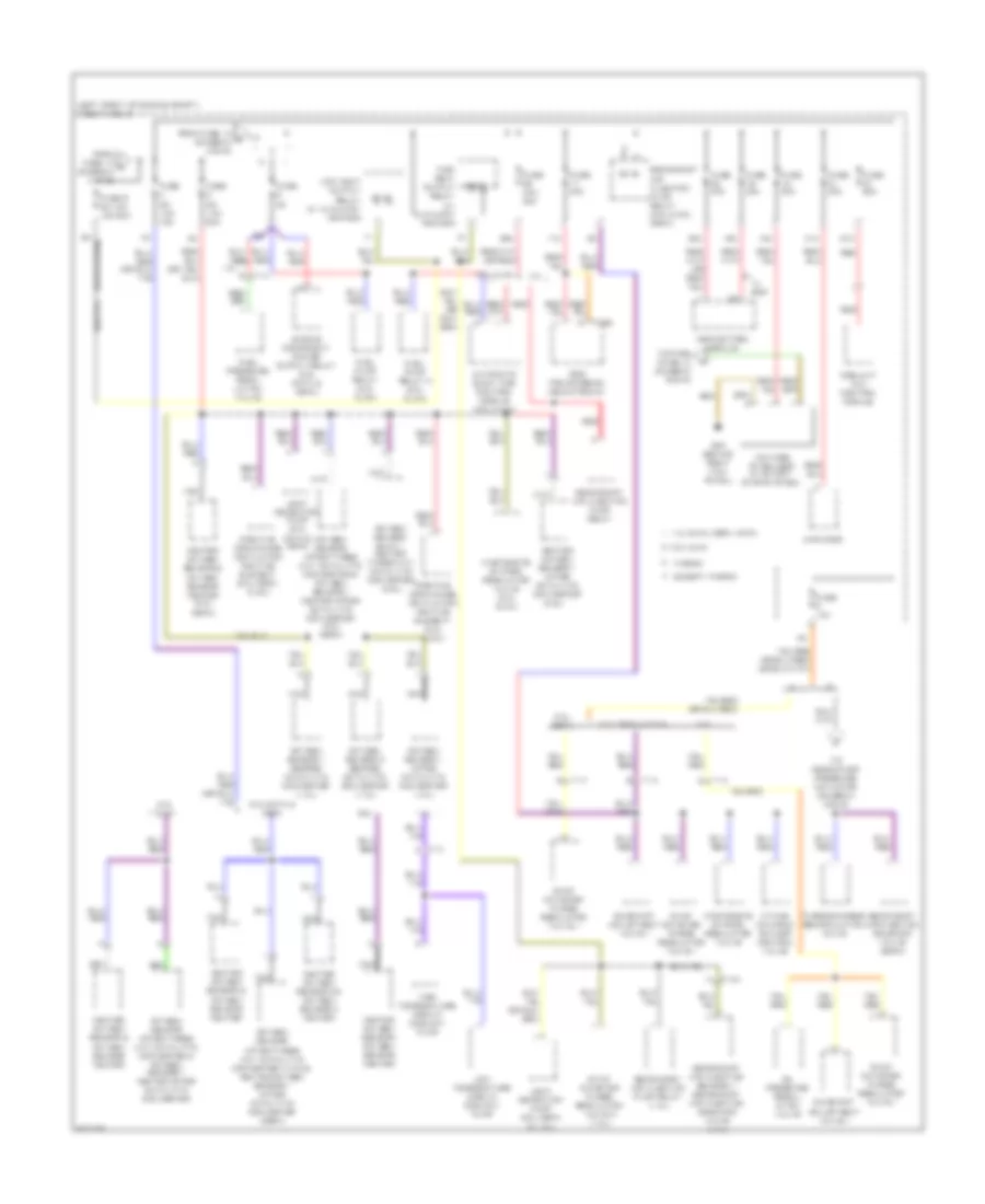
Power Distribution Wiring Diagram (3 of 6) for Volkswagen Jetta Hybrid SEL 2013
List of elements for Power Distribution Wiring Diagram (3 of 6) for Volkswagen Jetta Hybrid SEL 2013:
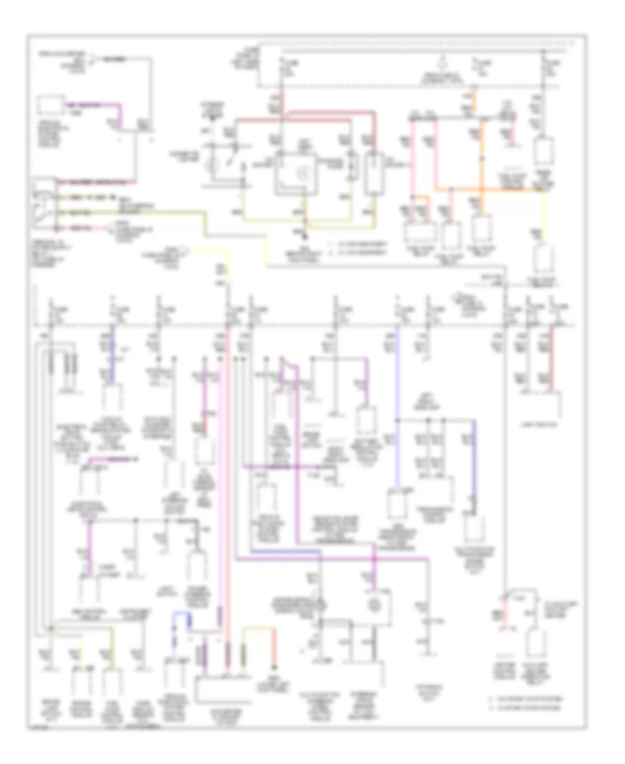
Power Distribution Wiring Diagram (4 of 6) for Volkswagen Jetta Hybrid SEL 2013
List of elements for Power Distribution Wiring Diagram (4 of 6) for Volkswagen Jetta Hybrid SEL 2013:
Power Distribution Wiring Diagram (5 of 6) for Volkswagen Jetta Hybrid SEL 2013
List of elements for Power Distribution Wiring Diagram (5 of 6) for Volkswagen Jetta Hybrid SEL 2013:
Power Distribution Wiring Diagram (6 of 6) for Volkswagen Jetta Hybrid SEL 2013
List of elements for Power Distribution Wiring Diagram (6 of 6) for Volkswagen Jetta Hybrid SEL 2013: