POWER DISTRIBUTION
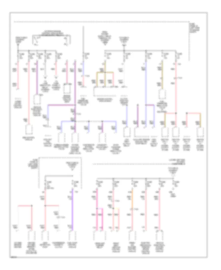
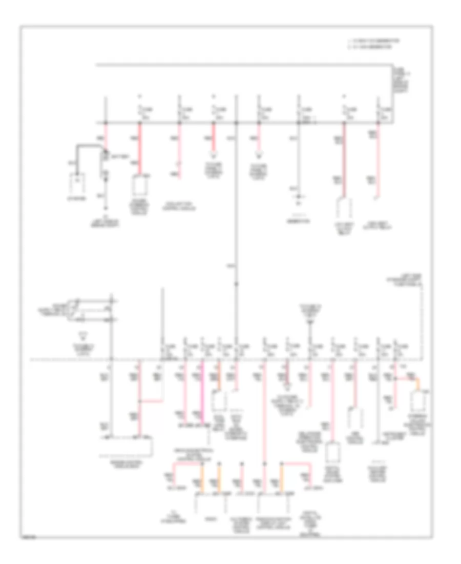
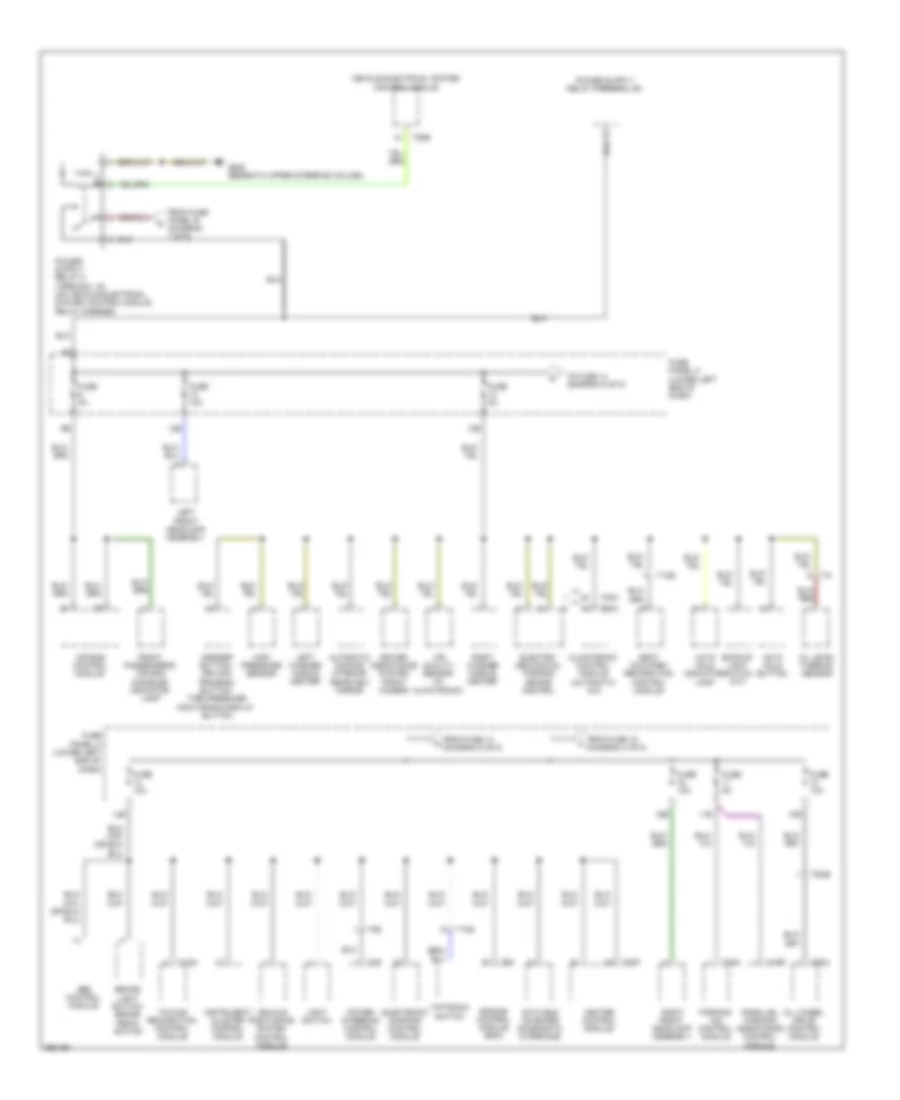
Power Distribution Wiring Diagram, Early Production (1 of 5) for Volkswagen Tiguan S 4Motion 2010

List of elements for Power Distribution Wiring Diagram, Early Production (1 of 5) for Volkswagen Tiguan S 4Motion 2010:
- (left side of engine compt) fuse panel b
- 52a
- 52c
- Abs control module
- Alarm horn relay
- Auxiliary heater control module
- Battery
- Cell phone operating electronics control module
- Coolant fan control module
- Data bus on board diagnostic interface
- Digital satellite radio tuner (if equipped)
- Digital sound system amplifier
- Engine control module (ecm)
- Fuse 10a (or 5a)
- Fuse 150a 200a
- Fuse 15a
- Fuse 20a
- Fuse 25a
- Fuse 30a
- Fuse 40a
- Fuse 50a
- Fuse 5a
- Fuse 80a
- Fuse panel a (left side of engine compt)
- G1 (left side of engine compt)
- Generator
- High heat output relay
- Instrument cluster
- Low heat output relay
- Multimedia system control module
- Nca
- Power steering control module
- Radio
- Radio/navigation display unit control module
- Red
- Starter
- Steering column electronics control module
- T12m
- T16b
- T20d
- T2a
- T2g
- T40
- T54g
- T8au
- T94
- To fuse 13 (diagram 2 of 5)
- To fuse 19 (diagram 2 of 5)
- To fuse panel c (diagram 3 of 5)
- To fuse panel c (diagram 4 of 5)
- Tv tuner (if equipped)
- Vehicle electrical system control module
- W/ 140a generator
- W/ 90a/110a generator
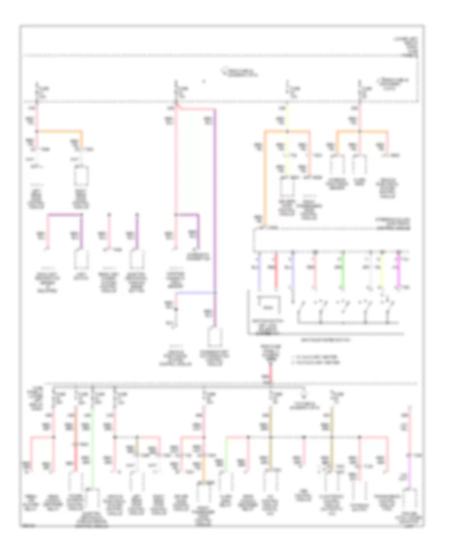
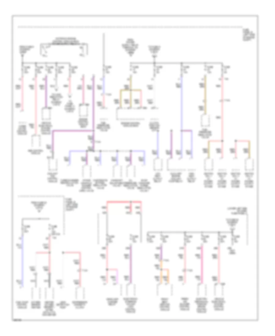
Power Distribution Wiring Diagram, Early Production (2 of 5) for Volkswagen Tiguan S 4Motion 2010
List of elements for Power Distribution Wiring Diagram, Early Production (2 of 5) for Volkswagen Tiguan S 4Motion 2010:
- (lower left end of dash) fuse panel c
- (not used)
- 48b
- 49b
- 50b
- 51b
- 52b
- 53b
- Abs control module
- Auxiliary engine coolant (ec) pump relay
- Camshaft adjustment valve 1
- Clutch position sensor (m/t)
- Compressor magnetic clutch
- Coolant fan control module
- Electro- mechanical parking brake control module
- Engine control module (ecm)
- Evap canister purge regulator valve 1
- Fresh air blower control module
- From fuse 22 (diagram 2 of 5)
- From fuse 9 (diagram 1 of 5)
- Front seat heating control module
- Fuel pressure regulator valve
- Fuel pressure regulator valve (if equipped)
- Fuel pump control module
- Fuse 10a
- Fuse 10a (or 15a)
- Fuse 15a
- Fuse 20a
- Fuse 25a
- Fuse 30a
- Fuse 40a
- Fuse 50a
- Fuse 5a
- Fuse panel b (left side of engine compt)
- Headlamp washer relay
- Heated oxygen sensor 1 after catalytic converter
- High heat output relay
- Ignition coil 1 w/ power output stage
- Ignition coil 2 w/ power output stage
- Ignition coil 3 w/ power output stage
- Ignition coil 4 w/ power output stage
- Intake manifold runner control (imrc) valve
- Leak detection pump
- Low heat output relay
- Oxygen sensor heater
- Red
- Red/
- T10a
- T10k
- T14a
- T40
- T52a
- T94
- To fuse 21 (diagram 2 of 5)
- To fuse 22 (diagram 3 of 5)
- To fuse panel c (diagram 4 of 5)
- To load reduction relay (diagram 4 of 5)
- Turbocharger recirculating valve
- Vehicle electrical system control module
- Wastegate bypass regulator valve
- Wiper motor control module
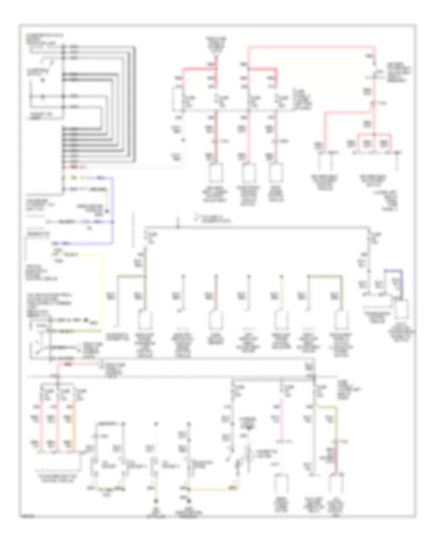
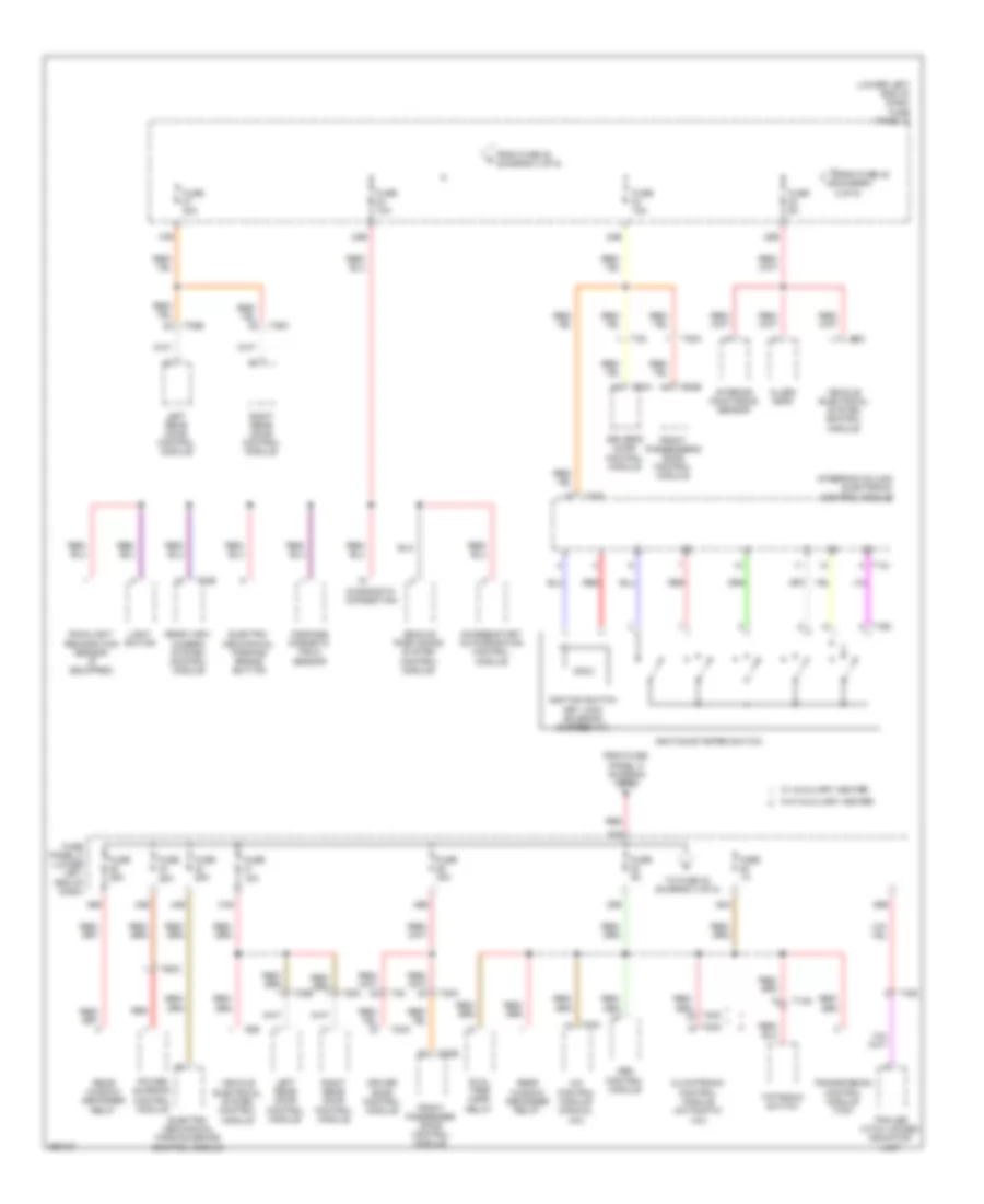
Power Distribution Wiring Diagram, Early Production (3 of 5) for Volkswagen Tiguan S 4Motion 2010
List of elements for Power Distribution Wiring Diagram, Early Production (3 of 5) for Volkswagen Tiguan S 4Motion 2010:
- (lower left end of dash) fuse panel c
- 20a
- 20b
- 21b
- 22b
- 23b
- 24b
- 43b
- 44b
- 45b
- 46b
- 47b
- 58a
- 58b
- A/c control module (manual a/c)
- Abs control module
- Access/start authorization control module
- Alarm horn
- Alarm horn relay
- Climatronic control module (automatic a/c)
- Compass magnetic field sensor
- Diagnostic connection
- Driver door control module
- Driver's door control module
- Electro- mechanical parking brake button
- Electro- mechanical parking brake control module
- Fresh air blower relay
- From fuse 20 (diagram 3 of 5)
- From fuse 48 (diagram 2 of 5)
- From fuse panel a (diagram 1 of 5)
- Front passenger door control module
- Front passenger's door control module
- Fuse 10a
- Fuse 15a
- Fuse 1a
- Fuse 25a
- Fuse 30a
- Fuse 5a
- Fuse panel c (lower left end of dash)
- Ignition switch key lock solenoid (6 speed a/t)
- Ignition/starter switch
- Interior monitoring sensor
- Left rear door control module
- Light switch
- Power sunroof control module
- Rain/light recognition sensor (if equipped)
- Rear view camera system control module
- Rear window defogger relay
- Red
- Right rear door control module
- Steering column electronic control module
- T10s
- T12j
- T16d
- T20a
- T20b
- T20c
- T20d
- T28
- T28a
- T28b
- T28c
- T2ib
- T52c
- T54b
- T6da
- Tiptronic switch
- To fuse 23 (diagram 3 of 5)
- Trailer hitch locked indicator lamp
- Transmission control module (tcm)
- Vehicle electrical system control module
- Vehicle positioning system control module
- W/ auxiliary heater
- W/o auxiliary heater
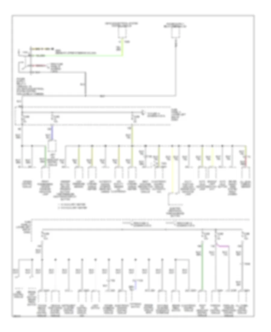
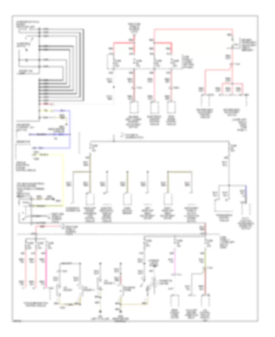
Power Distribution Wiring Diagram, Early Production (4 of 5) for Volkswagen Tiguan S 4Motion 2010
List of elements for Power Distribution Wiring Diagram, Early Production (4 of 5) for Volkswagen Tiguan S 4Motion 2010:
- (lower left end of dash) fuse panel c
- (on vehicle electrical system control module relay carrier) load reduction relay
- (rear center console) g688
- 12v socket
- 12v socket 2
- 12v socket 3
- 15b
- 25b
- 28a
- 28b
- 29b
- 30a
- 31b
- 40a
- 40b
- 41b
- 42b
- 54a
- 54b
- 55a
- 55b
- 56a
- 56b
- 57a
- 57b
- A/c control module (manual a/c)
- Auxiliary heater operation relay
- Blocking diode
- Cigarette lighter
- Converter w/ socket, 12v- 230v/115v
- Diagnostic connection
- Driver's power seat adjustment circuit breaker 1
- Driver's seat adjustment control module
- Driver's seat adjustment switch
- Driver's seat lumbar support adjustment
- Electro- mechanical parking brake control module
- Electronic damping control module
- From fuse panel a (diagram 1 of 5)
- From fuse panel b (diagram 2 of 5)
- Fuse 10a
- Fuse 15a
- Fuse 20a
- Fuse 25a
- Fuse 30a
- Fuse 40a
- Fuse panel c (lower left end of dash)
- G61 (left "c" pillar)
- G684
- G688 (rear center console)
- Generator
- Headlamp range control adjuster
- Headlamp range/ cornering lamp control module
- Instrument panel & switch illumination dimmer switch
- Interior lights system
- Inverter switch
- Inverter switch & socket indicator lamp
- Left headlamp beam adjustment motor
- Mass air flow sensor
- Multi- function transmission range (tr) switch
- Nca
- Rear window wiper motor
- Red
- Right headlamp beam adjustment motor
- Roof shade control module
- Socket ind lamp
- Switch
- T10a
- T10k
- T12fv
- T12m
- T17l
- T2fo
- T52b
- T52c
- T6da
- T6w
- To fuse 16 (diagram 5 of 5)
- Towing recognition control module
- Transmission control module
- Vehicle electrical system control module
Power Distribution Wiring Diagram, Early Production (5 of 5) for Volkswagen Tiguan S 4Motion 2010
List of elements for Power Distribution Wiring Diagram, Early Production (5 of 5) for Volkswagen Tiguan S 4Motion 2010:
- 10b
- 11b
- 12b
- 13b
- 14b
- 16b
- A/c control module (manual a/c)
- Abs control module
- Air bag control module
- Air quality sensor (w/ climatronic)
- All wheel drive control module
- Asr/esp button/ driving program button/ tire pressure monitoring display button
- Auto hold button
- Auto hold indicator lamp
- Automatic dimming interior rearview mirror
- Backup light switch (m/t)
- Brake light switch/ brake pedal switch
- Brake pedal switch
- Climatronic control module
- Climatronic control module (automatic a/c)
- Data bus on board diagnostic interface
- Driver assist- ance system front camera
- Electro- mechanical parking brake button
- Electronic damping control module
- Engine control module (ecm)
- From fuse 13 (diagram 5 of 5)
- From fuse 15 (diagram 4 of 5)
- From fuse panel b (diagram 1 of 5)
- Front passenger's air bag disabled indicator lamp
- Fuse 10a
- Fuse 5a
- Fuse panel c (lower left end of dash)
- G605 (beneath upper steering column)
- High pressure sensor
- Instrument cluster control module
- Left hid headlamp control module
- Left washer nozzle heater
- Light switch
- Multi- function module & engine cold indicator lamp
- Oil level thermal sensor
- Parallel parking assistance control module
- Parking aid control module
- Power steering control module
- Right hid headlamp control module
- Right washer nozzle heater
- Seat occupied recognition control module
- T10e
- T10s
- T12m
- T16h
- T16r
- T20c
- T3z
- T52b
- T6ab
- T6z
- T8za
- T94
- Tiptronic switch
- To fuse 14 (diagram 5 of 5)
- Towing recog- nition control module
- Vehicle electrical system control module
- Vehicle positioning system control module
- W/ auxiliary heater
- W/o auxiliary heater
Power Distribution Wiring Diagram, Late Production (1 of 5) for Volkswagen Tiguan S 4Motion 2010
List of elements for Power Distribution Wiring Diagram, Late Production (1 of 5) for Volkswagen Tiguan S 4Motion 2010:
- (left side of engine compt) fuse panel b
- 52a
- 52c
- Abs control module
- Auxiliary heater control module
- Battery
- Cellphone operating electronics control module
- Coolant fan control module
- Data bus on board diagnostic interface
- Digital satellite radio tuner (if equipped)
- Digital sound system amplifier
- Dual tone horn relay
- Engine control module (ecm)
- Fuse 10a (or 5a)
- Fuse 150a 200a
- Fuse 15a
- Fuse 25a
- Fuse 30a
- Fuse 40a
- Fuse 50a
- Fuse 5a
- Fuse 80a
- Fuse panel a (left side of engine compt)
- G1 (left side of engine compt)
- Generator
- High heat output relay
- Instrument cluster
- Low heat output relay
- Multimedia system control module
- Nca
- Power steering control module
- Radio
- Radio/navigation display unit control module
- Red
- Starter
- Steering column electronics control module
- T12m
- T16b
- T16l
- T2a
- T2g
- T40
- T54g
- T8au
- T94
- To fuse 13 (diagram 2 of 5)
- To fuse 19 (diagram 2 of 5)
- To fuse panel c (diagram 3 of 5)
- To fuse panel c (diagram 4 of 5)
- Tv tuner (if equipped)
- Vehicle electrical system control module
- W/ 140a generator
- W/ 90a/110a generator
Power Distribution Wiring Diagram, Late Production (2 of 5) for Volkswagen Tiguan S 4Motion 2010
List of elements for Power Distribution Wiring Diagram, Late Production (2 of 5) for Volkswagen Tiguan S 4Motion 2010:
- (lower left end of dash) fuse panel c
- (not used)
- 38a
- 38b
- 39a
- 39b
- 48b
- 49b
- 50b
- 51b
- 52a
- 52b
- 53b
- Abs control module
- Auxiliary engine coolant pump relay
- Camshaft adjustment valve 1
- Clutch position sensor (m/t)
- Compressor magnetic clutch
- Coolant fan control module
- Electro- mechanical parking brake control module
- Electronic steering column lock control module
- Engine control module (ecm)
- Evap canister purge regulator valve 1
- Fresh air blower control module
- From fuse 22 (diagram 2 of 5)
- From fuse 9 (diagram 1 of 5)
- Front seat heating control module
- Fuel pressure regulator valve
- Fuel pump control module
- Fuse 10a
- Fuse 10a (or 15a)
- Fuse 15a
- Fuse 20a
- Fuse 25a
- Fuse 30a
- Fuse 40a
- Fuse 50a
- Fuse 5a
- Fuse panel b (left side of engine compt)
- Headlamp washer relay
- Heated oxygen sensor 1 after catalytic converter
- High heat output relay
- Ignition coil 1 w/ power output stage
- Ignition coil 2 w/ power output stage
- Ignition coil 3 w/ power output stage
- Ignition coil 4 w/ power output stage
- Intake manifold runner control (imrc) valve
- Leak detection pump
- Low heat output relay
- Nca
- Oil pressure regulation valve
- Oxygen sensor heater
- Red
- T10a
- T10k
- T14a
- T40
- T94
- To fuse 21 (diagram 2 of 5)
- To fuse 22 (diagram 3 of 5)
- To fuse panel c (diagram 4 of 5)
- To load reduction relay (diagram 4 of 5)
- Turbocharger recirculation valve
- Vehicle electrical system control module
- Wastegate bypass regulator valve
- Wiper motor control module
Power Distribution Wiring Diagram, Late Production (3 of 5) for Volkswagen Tiguan S 4Motion 2010
List of elements for Power Distribution Wiring Diagram, Late Production (3 of 5) for Volkswagen Tiguan S 4Motion 2010:
- (lower left end of dash) fuse panel c
- 20a
- 20b
- 21b
- 22b
- 23b
- 24b
- 43b
- 44b
- 45b
- 46b
- 47b
- 52b
- 52c
- 58a
- 58b
- A/c control module (manual a/c)
- Abs control module
- Access/start authorization control module
- Alarm horn
- Climatronic control module (automatic a/c)
- Compass magnetic field sensor
- Diagnostic connection
- Driver door control module
- Driver's door control module
- Dual tone horn relay
- Electro- mechanical parking brake button
- Electro- mechanical parking brake control module
- From fuse 20 (diagram 3 of 5)
- From fuse 48 (diagram 2 of 5)
- From fuse panel a (diagram 1 of 5)
- Front passenger door control module
- Front passenger's door control module
- Fuse 10a
- Fuse 15a
- Fuse 1a
- Fuse 25a
- Fuse 30a
- Fuse 5a
- Fuse panel c (lower left end of dash)
- Ignition switch key lock solenoid (6 speed a/t)
- Ignition/starter switch
- Interior monitoring sensor
- Left rear door control module
- Light switch
- Power sunroof control module
- Rain/light recognition sensor (if equipped)
- Rear view camera system control module
- Rear window defogger relay
- Red
- Right rear door control module
- Steering column electronic control module
- T10s
- T12j
- T16d
- T20a
- T20b
- T20c
- T20d
- T28
- T28a
- T28b
- T28c
- T2ib
- T54b
- T6da
- Tiptronic switch
- To fuse 23 (diagram 3 of 5)
- Trailer hitch locked indicator lamp
- Transmission control module (tcm)
- Vehicle electrical system control module
- Vehicle positioning system control module
- W/ auxiliary heater
- W/o auxiliary heater
Power Distribution Wiring Diagram, Late Production (4 of 5) for Volkswagen Tiguan S 4Motion 2010
List of elements for Power Distribution Wiring Diagram, Late Production (4 of 5) for Volkswagen Tiguan S 4Motion 2010:
- (lower left end of dash) fuse panel c
- (on vehicle electrical system control module relay carrier) load reduction relay
- 12v socket
- 12v socket 2
- 12v socket 3
- 15b
- 25b
- 28a
- 28b
- 29b
- 30a
- 31b
- 40a
- 40b
- 41b
- 42b
- 54a
- 54b
- 55a
- 55b
- 56a
- 56b
- 57a
- 57b
- A/c control module (manual a/c)
- Auxiliary heater operation relay
- Blocking diode
- Cigarette lighter
- Converter w/ socket, 12v- 230v/115v
- Diagnostic connection
- Driver's power seat adjustment circuit breaker 1
- Driver's seat adjustment control module
- Driver's seat adjustment switch
- Driver's seat lumbar support adjustment switch
- Electro- mechanical parking brake control module
- Electronic damping control module
- From fuse panel a (diagram 1 of 5)
- From fuse panel b (diagram 2 of 5)
- Fuse 10a
- Fuse 15a
- Fuse 20a
- Fuse 25a
- Fuse 30a
- Fuse 40a
- Fuse panel c (lower left end of dash)
- G61 (left "c" pillar)
- G684
- G688 (rear center console)
- Generator
- Headlamp range/ cornering lamp control module
- Instrument panel & switch illumination dimmer switch
- Interior lights system
- Inverter switch
- Inverter switch & socket indicator lamp
- Left headlamp beam adjustment motor
- Mass air flow sensor
- Multi- function transmission range (tr) switch
- Nca
- Rear window wiper motor
- Red
- Right headlamp beam adjustment motor
- Roof shade control module
- Socket ind lamp
- T10a
- T10k
- T12fv
- T12n
- T17l
- T2fo
- T52b
- T52c
- T6da
- T6w
- To fuse 16 (diagram 5 of 5)
- Towing recognition control module
- Transmission control module
- Vehicle electrical system control module
Power Distribution Wiring Diagram, Late Production (5 of 5) for Volkswagen Tiguan S 4Motion 2010
List of elements for Power Distribution Wiring Diagram, Late Production (5 of 5) for Volkswagen Tiguan S 4Motion 2010:
- 10b
- 11b
- 12b
- 13b
- 14b
- 16b
- Abs control module
- Air bag control module
- Air quality sensor (w/ climatronic)
- All wheel drive control module
- Asr/esp button/ driving program button/ tire pressure monitoring display button
- Auto hold button
- Auto hold indicator lamp
- Automatic dimming interior rearview mirror
- Backup light switch (m/t)
- Brake light switch/ brake pedal switch
- Climatronic control module (automatic a/c)
- Data bus on board diagnostic interface
- Driver assistance system front camera
- Electro- mechanical parking brake control
- Electronic damping control module
- Engine control module (ecm)
- From fuse 13 (diagram 5 of 5)
- From fuse 15 (diagram 4 of 5)
- From fuse panel b (diagram 1 of 5)
- Front passenger's air bag disabled indicator lamp
- Fuse 10a
- Fuse 5a
- Fuse panel c (lower left end of dash)
- G605 (beneath upper steering column)
- Heater control module
- High pressure sensor
- Instrument cluster control module
- Left front headlamp assembly
- Left washer nozzle heater
- Light switch
- Oil level thermal sensor
- Parallel parking assistance control module
- Parking aid control module
- Power steering control module
- Right front headlamp assembly
- Right washer nozzle heater
- Seat occupied recognition control module
- T10e
- T10s
- T12m
- T16h
- T16r
- T20c
- T20f
- T3z
- T52b
- T6ab
- T6z
- T8za
- T94
- Tiptronic switch
- To fuse 14 (diagram 5 of 5)
- Towing recognition control module
- Vehicle electrical system control module
- Vehicle positioning system control module