POWER DISTRIBUTION
Accessories Connector Wiring Diagram for Volvo 850 T-5 1997

List of elements for Accessories Connector Wiring Diagram for Volvo 850 T-5 1997:
- Accessories connector (left side of i/p)
- Central electrical unit (left rear of engine compt)
- Dim out
- Fuse 16 30a
- Fuse 20 15a
- Fuse 35 10a
- Hot at all times
- Hot in acc or run
- Hot w/ hi-beam headlamps on
- Interior lights system
- Pnk
- Power ground connector
- Red
- Rheostat
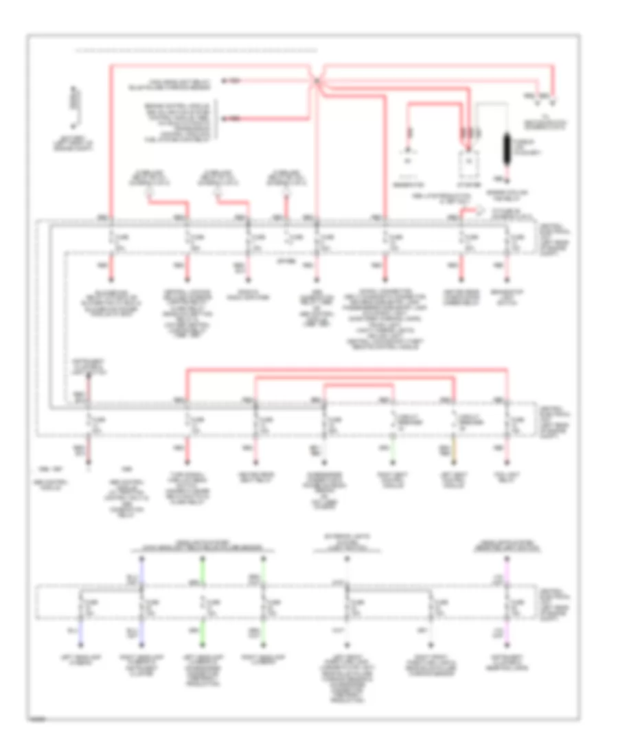
Power Distribution Wiring Diagram (1 of 2) for Volvo 850 T-5 1997
List of elements for Power Distribution Wiring Diagram (1 of 2) for Volvo 850 T-5 1997:
- (30-rail connector) obd (ii) diagnostic connector, driver's side entry lamp, passengers's side entry lamp, glove box light, door open warning lamps, trunk light, vanity mirror lights, ceiling light, central locking/anti-theft remote control module
- (spare)
- 1996 late production & 1997 only
- 1996, 1997
- Abs combination relay (1995) or abs control module (1996, 1997)
- Abs control module
- Abs control module (w/ traction control only) & abs combination relay
- Accessories connector & power antenna (sedan) or not used (wagon)
- Battery (left front of engine compt)
- Blower fan relay (w/o ecc) or blower fan (w/ ecc) & blower fan power module (w/ ecc)
- Brake/stop light switch
- Central electrical unit (left rear of engine compt)
- Central locking/ delayed interior lighting relay, alarm relay deadlock setting relay & 2-stage central locking relay (1996, 1997)
- Circuit breaker
- Engine control module, ezk (di) ignition system control module (1995), aw 50-42 automatic transmission control module & fuel system main relay
- Engine cooling fan relay
- Exterior lights system (light switch)
- Fog light relay
- Fuse
- Fuse 10a
- Fuse 15a
- Fuse 25a
- Fuse 30a
- Generator
- Headlights system (main headlight relay/bulb failure sensor)
- Headlights system (rear fog light switch)
- Heated rear seat relay
- Heated rear window/door mirror relay
- Instrument cluster & light switch
- Instrument cluster & rear fog lamps
- Left front park/turn lamp, license plate light, rear bulb failure warning sensor & accessories connector- (1995 early production)
- Left headlamp (hi-beam)
- Left headlamp (lo-beam) & accessories connector- (1995 early production)
- Left seat control module
- Main headlight relay/ bulb failure warning sensor
- Overload relay #1 (x+) (diagram 2 of 2)
- Overload relay #2 (15+) (diagram 2 of 2)
- Overload relay #3 (x+) (diagram 2 of 2)
- Radio & radio amplifier
- Red
- Right front park/turn lamp & rear bulb failure warning sensor
- Right headlamp (hi-beam) & instrument cluster
- Right headlamp (lo-beam)
- Right seat control module
- Starter
- To fuse 36 (diagram 2 of 2)
- To ignition switch (diagram 2 of 2)
- Turn signal/ high-low beam switch, hazard flasher relay/switch & alarm relay
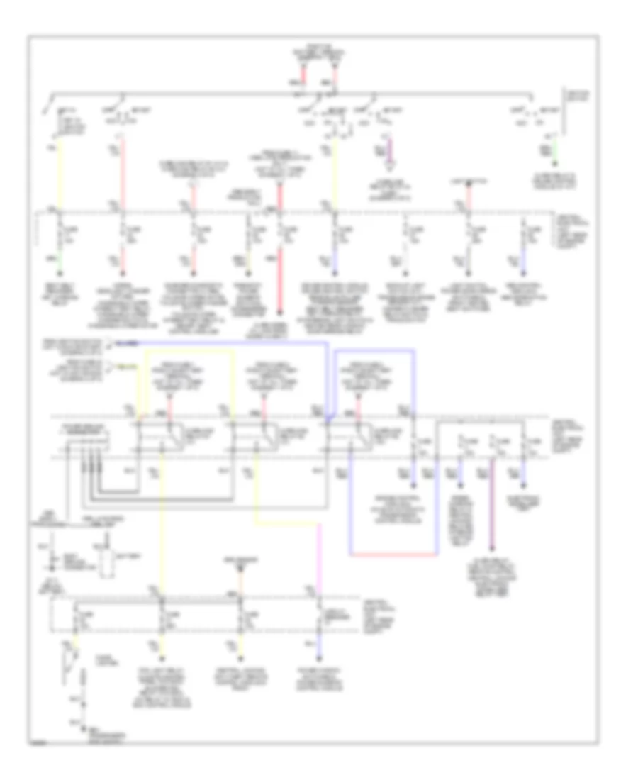
Power Distribution Wiring Diagram (2 of 2) for Volvo 850 T-5 1997
List of elements for Power Distribution Wiring Diagram (2 of 2) for Volvo 850 T-5 1997:
- 15i
- 1995 late prod, 1996, 1997
- 1996 early production only
- Abs control module & abs combination relay
- Acc
- Alarm relay & cruise control module (w/ a/t)
- Alarm relay, fuel pump relay, remote control central locking/ electronic immobilizer relay (1997)
- Alarm siren (w/ late prod guard alarm ii)
- Back-up light switch (m/t), transmission range sensor (a/t), hazard flasher relay/switch & tracs switch
- Battery
- Body ground connector
- Central electrical unit (left rear of engine compt)
- Central locking/ anti-theft remote control module & radio
- Cigar lighter
- Circuit breaker
- Cruise control module, cruise control switch, rear bulb failure warning sensor, seat belt reminder/ key warning relay, stop/brake light switch & heated rear window/ door mirrors relay
- Early production
- Electronic immobilizer (1997)
- Engine control module & aw 50-42 automatic transmission control module
- Fog light relay, climate control panel (w/o ecc), blower fan relay (w/o ecc), a/c relay (w/ ecc) & ecc control module
- From fuse 11 (1996 late production only) (hot at all times) (diagram 1 of 2)
- From fuse 33 (ignition switch f (hot in acc or run) (diagram 2 of 2)
- From fuse 6 (positive battery terminal) (hot at all times) (diagram 1 of 2)
- From fuse 7 (positive battery terminal) (hot at all times) (diagram 1 of 2)
- From fuse 8 (positive battery terminal) (hot at all times) (diagram 1 of 2)
- From ignition switch (hot in run or start) (diagram 2 of 2)
- Fuse 10a
- Fuse 15a
- Fuse 25a
- G111 (below battery)
- G901 (passenger's side a-post)
- Horns, headlight washer motors, windshield wiper intermittent relay, windshield wiper/ washer switch & windshield wiper motor
- Ignition switch
- Key in ignition switch
- Key-in
- Light switch
- Light switch, power door mirror switches & front heated seat switches
- Off
- On-board diagnostic connector a (1995), tailgate wiper motor, tailgate wiper/washer switch, tailgate wiper intermittent relay & memory seat control modules
- Overload relay #1 (x+)
- Overload relay #1 (x+) & overload relay #3 (x+) (diagram 2 of 2)
- Overload relay #2 (15+)
- Overload relay #2 (x+) & fuse 1 (diagram 2 of 2)
- Overload relay #3 (x+)
- Positive battery terminal (diagram 1 of 1)
- Power ground connector
- Power window switches & power sunroof control module
- Red
- Rheostat, power sunroof switch & accessories connector
- Seat belt reminder/ key warning relay
- Speed warning relay & central locking/ delayed interior lighting relay
- Srs sensor unit
- Start