POWER DISTRIBUTION
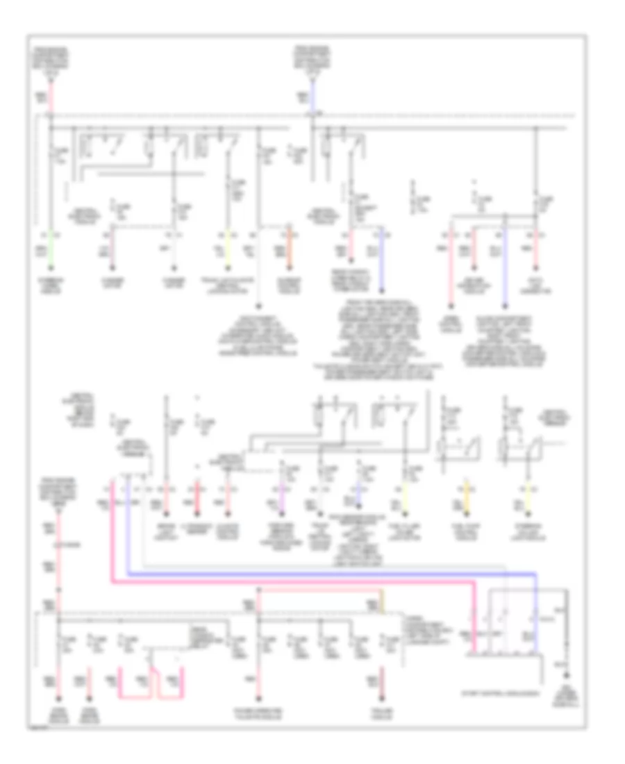
Power Distribution Wiring Diagram (1 of 3) for Volvo S80 T-6 2012

List of elements for Power Distribution Wiring Diagram (1 of 3) for Volvo S80 T-6 2012:
- Accelerator pedal sensor
- Alternator control module & starter motor
- Auto dimming rearview mirror
- Auxiliary lights relay
- Battery
- Battery fuses
- Brake control module
- Central electronic module
- Central electronic module (behind right end of dash)
- Climate control system relay
- Cooling fan control module
- Electronic power steering control module
- Engine compartment distribution box (at left side of engine compt, forward of strut tower)
- Engine control module
- Engine management system main relay
- Feed relay
- Forward aimed radar
- Forward sensing module
- From a fuse a7 (diagram 1 of 3)
- Fuse a1 50a
- Fuse a2 50a
- Fuse a3 60a
- Fuse a4 60a
- Fuse a43 80a
- Fuse a5 60a
- Fuse a6 (not used)
- Fuse a7 100a
- Fuse b11 40a
- Fuse b12 (not used)
- Fuse b13 40a
- Fuse b14 20a
- Fuse b16 10a
- Fuse b17 20a
- Fuse b18 5a
- Fuse b19 5a
- Fuse b20 10a
- Fuse b21 10a
- Fuse b23 5a
- Fuse b27 5a
- Fuse b28 20a
- Fuse b29 15a
- Fuse b30 10a
- Fuse b31 15a
- Fuse b32 15a
- Fuse b34 30a
- Fuse b8 20a
- Fuse b9 30a
- Fuse f18 10a
- Fuse f19 5a
- Fuse f20 7.5a
- Fuse pf1 150a
- Fuse pf2 150a
- G3 (left rear of engine compt)
- Headlight washer motor relay
- Horn relay
- Left front lamp housing & right front lamp housing
- Left heated windshield washer nozzle & right heated windshield washer nozzle
- Light switch module
- Nca
- Occupant weight sensor
- Passenger compartment fan control module & passenger compartment fan motor
- Ptc element
- Red
- Starter motor relay
- To cargo compartment fuse box (diagram 2 of 3)
- To central electronic module (diagram 2 of 3)
- To fuse a43 (diagram 1 of 3)
- To passenger compartment distribution box (diagram 3 of 3)
- Transmission control module
- Wiper motor module
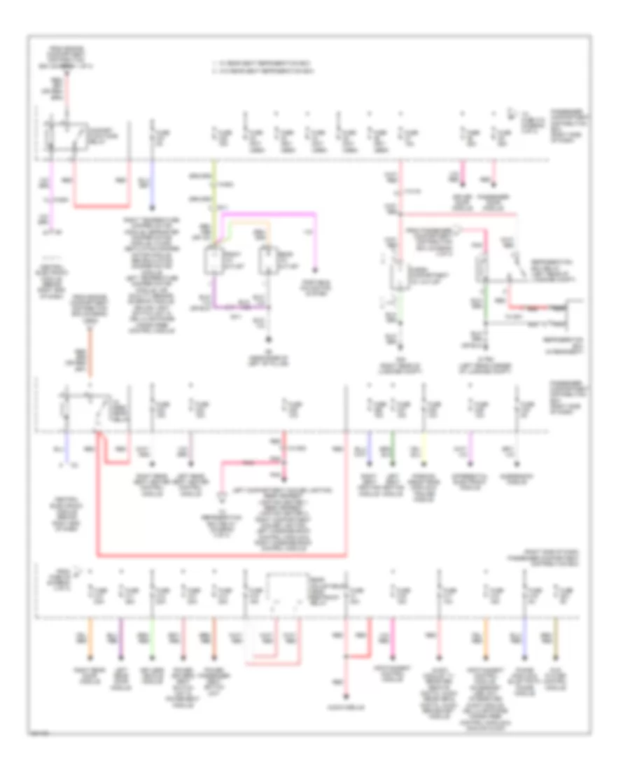
Power Distribution Wiring Diagram (2 of 3) for Volvo S80 T-6 2012
List of elements for Power Distribution Wiring Diagram (2 of 3) for Volvo S80 T-6 2012:
- 74/413
- 74/504b
- Brake light contact
- Cargo compartment distribution box (left side of luggage compt)
- Central electronic module
- Central electronic module (behind right end of dash)
- Climate control module
- Data link connector
- Driver information module
- Forward sensing module & forward-aimed radar
- From engine compartment distribution box (diagram 1 of 3)
- Front driver's side sill lighting (s80), rear driver's side sill lighting (s80), front passenger side sill lighting (s80), rear passenger side sill lighting (s80), left side cargo compartment lighting (s80), right side cargo compartment lighting (s80), power driver's seat switch unit, power seat module, tailgate closing switch (except s80 & w/ pot), power passenger seat switch unit & driver's door power window switches
- Fuel filler cover lock motor
- Fuel pump control module
- Fuse a1 30a
- Fuse a11 40a
- Fuse a2 30a
- Fuse a3 30a
- Fuse a4 (not used)
- Fuse a5 30a
- Fuse a6 (not used)
- Fuse a7 (not used)
- Fuse a8 (not used)
- Fuse f1 (except s80) 15a
- Fuse f10 15a
- Fuse f11 (s80) 10a
- Fuse f11 10a
- Fuse f13 20a
- Fuse f14 5a
- Fuse f15 15a
- Fuse f16 5a
- Fuse f21 15a
- Fuse f22 5a
- Fuse f23 20a
- Fuse f24 5a
- Fuse f3 7.5a
- Fuse f4 5a
- Fuse f5 10a
- Fuse f6 7.5a
- Fuse f7 7.5a
- Fuse f8 10a
- Fuse f9 15a
- G83 (under driver's door sill)
- Glove compartment lighting, left front courtesy lighting, right front courtesy lighting, driver's side sill moldings converter/control module & passenger side sill moldings converter/control module
- Infotainment control module, accessory usb unit, integrated audio module, dvd player/control module & cellular phone hands free control module
- Park brake module
- Power operated tailgate module
- Rain sensor module, rear reading light, left vanity mirror lighting, right vanity mirror lighting & ceiling light switch unit
- Rear window defroster relay
- Rear window wiper relay & rear window wiper motor
- Red
- Siren control module
- Start control module (scm)
- Steering column lock module
- Steering wheel module
- Sunroof control module
- Trailer module
- Trunk lid central locking motor
- Trunk lid/tailgate central locking motor
- Ultrasonic sensor
- Washer motor
Power Distribution Wiring Diagram (3 of 3) for Volvo S80 T-6 2012
List of elements for Power Distribution Wiring Diagram (3 of 3) for Volvo S80 T-6 2012:
- (right side of dash) passenger compartment distribution box
- 17x/19
- 74/1500
- 74/1501
- 74/502
- 74/504
- 9x/1
- Audio module
- Audio module, tv receiver, remote digital audio receiver & digital audio broadcast module
- Cargo compartment 12v outlet
- Central electronic module (behind right end of dash)
- Comfort functions relay
- Differential electronic module
- Driver door module
- Dvd player control module
- Feed rear relay
- From engine compartment distribution box (diagram 1 of 3)
- From g fuse c9 (diagram 3 of 3)
- From passenger h compartment distribution box (diagram 3 of 3)
- Front 12v outlet
- Fuse c1 40a
- Fuse c10 25a
- Fuse c11 25a
- Fuse c12 20a
- Fuse c13 20a
- Fuse c14 20a
- Fuse c15 15a
- Fuse c16 15a
- Fuse c17 10a
- Fuse c18 15a
- Fuse c19 5a
- Fuse c2 (not used)
- Fuse c20 5a
- Fuse c21 5a
- Fuse c22 15a
- Fuse c23 15a
- Fuse c24 15a
- Fuse c25 10a
- Fuse c26 15a
- Fuse c27 15a
- Fuse c28 10a
- Fuse c29 10a
- Fuse c3 (not used)
- Fuse c30 5a
- Fuse c4 (not used)
- Fuse c5 (not used)
- Fuse c6 (not used)
- Fuse c7 15a
- Fuse c8 25a
- Fuse c9 25a
- G-trm (left rear corner of luggage compt)
- G48 (right rear of luggage compt)
- G6 (near base of left "b" pillar)
- Infotainment control module
- Infotainment control module, accessory usb unit, integrated audio module, cellular phone hands free control module & analog clock
- Keyless vehicle module
- Left compartment cooler lighting, rear armrest lighting center 1, rear armrest lighting center 2, right compartment cooler lighting, left massage back control module & right massage back control module
- Left rear door module
- Left rear seat heater control module
- Left seat heating module
- Nca
- Parking assistance module & trailer module
- Passenger compartment distribution box (right side of dash)
- Passenger door module
- Pnk
- Portable navigation system
- Power driver's seat switch unit & power seat module
- Power passenger seat switch unit
- Rear 12v outlet
- Rear adjustable head restraint relay
- Red
- Refrigeration box (in rear seat)
- Refrigeration box relay (left rear of luggage compt)
- Right rear door module
- Right rear seat heater control module
- Right seat heating module
- Right temperature damper motor module, defroster damper motor module, floor/ ventilation damper motor module, recirculation damper motor module, left temperature damper motor module, air quality sensor, sunroof module, ceiling light switch unit & cellular phone hands free control module
- Suspension module
- To fuse c10 (diagram 3 of 3)
- To refrigeration box relay (diagram 3 of 3)
- W/ rear seat refrigeration box
- W/o rear seat refrigeration box