POWER DISTRIBUTION
Power Distribution Wiring Diagram (1 of 2) for Volvo V70 2005

List of elements for Power Distribution Wiring Diagram (1 of 2) for Volvo V70 2005:
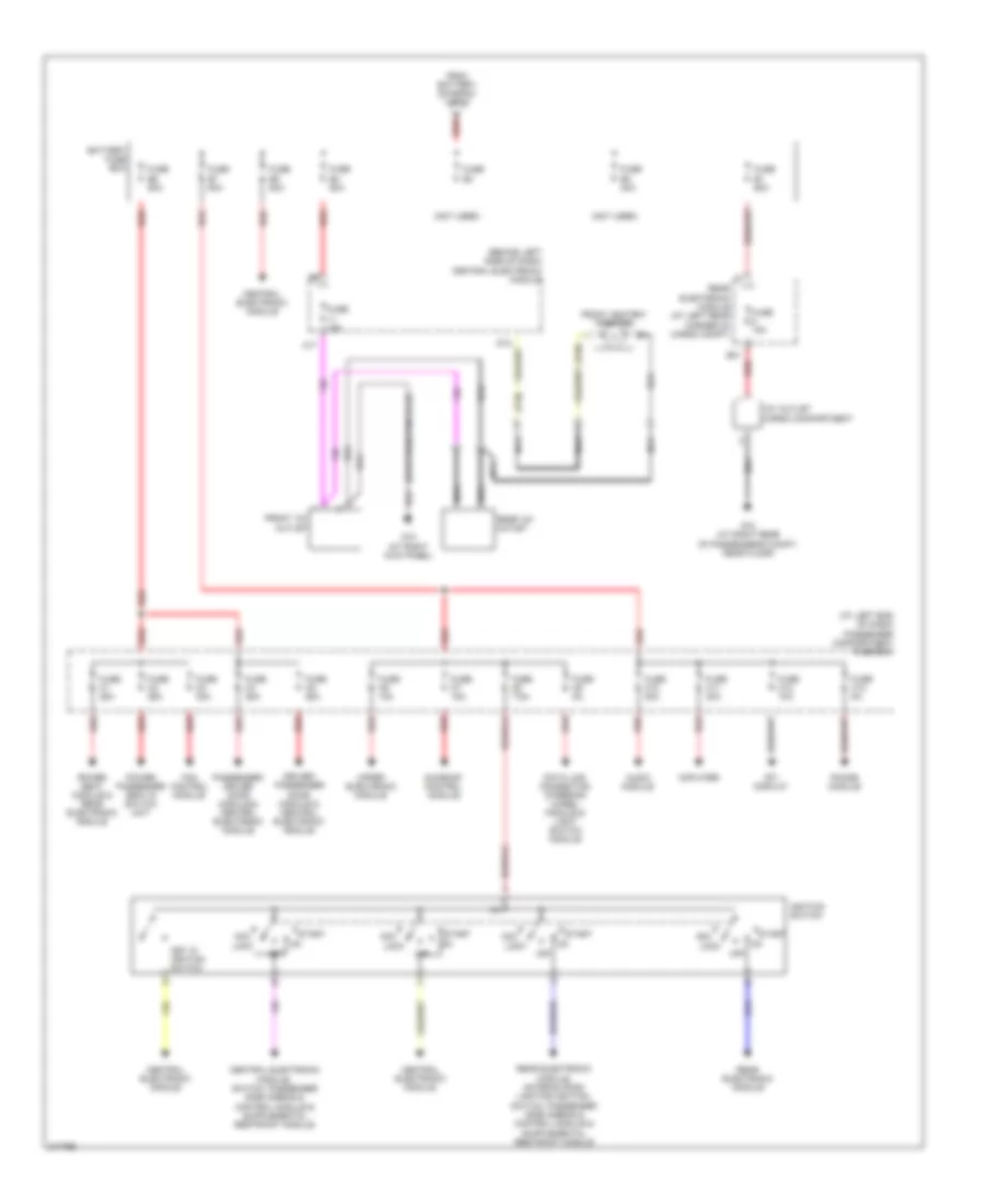
Power Distribution Wiring Diagram (2 of 2) for Volvo V70 2005
List of elements for Power Distribution Wiring Diagram (2 of 2) for Volvo V70 2005: