POWER DISTRIBUTION
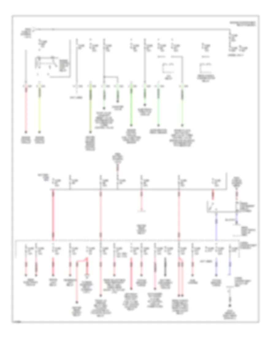
Power Distribution Wiring Diagram (1 of 3) for Volvo V70 T-5 2001

List of elements for Power Distribution Wiring Diagram (1 of 3) for Volvo V70 T-5 2001:
- red
- (not used)
- Abs control module
- Accessory (auxiliary light)
- Alarm siren
- Automatic transmission, extended x feed relay
- Battery
- Brake light contact
- C21
- C22
- C24
- C25
- C28
- C30
- Capacitor
- Central electronic module
- Combustion preheater module
- Data link connector, light switch module, climate control module, steering wheel module
- Electric cooling fan control module
- Engine compartment relay/fuse box
- Extended x feed relay
- Fan control module
- From ignition switch (diagram 3 of 3)
- Fuel pump relay
- Fuse a2 60a
- Fuse a3 60a
- Fuse a4 60a
- Fuse a7 60a
- Fuse b1 25a
- Fuse b12 5a
- Fuse b13 25a
- Fuse b14 30a
- Fuse b16 15a
- Fuse b17
- Fuse b18
- Fuse b19 30a
- Fuse b2 15a
- Fuse b22 15a
- Fuse b9 15a
- Fuse c21 10a
- Fuse c22 20a
- Fuse c23 5a
- Fuse c24 10a
- Fuse c25 10a
- Fuse c26 30a
- Fuse c27 15a
- Fuse c28 10a
- Fuse c29 10a
- Fuse c30 10a
- Fuse c31 10a
- Fuse c32 10a
- Fuse c33 15a
- Fuse c34 15a
- Fuse c35 25a
- Fuse c36 25a
- Fuse c37 30a
- Fuse c38 5a
- G104 (rear of left front fender)
- Generator
- Horn relay
- Intermittent windshield wiper relay
- Jump start terminal
- Left front door control module
- Left front door control module, right front door control module
- Left front parking light, left front side marker light
- Low/high speed windshield wiper relay
- Mobile telephone
- Parking lamps relay
- Parking light relay
- Parking light rem shunt
- Passenger compartment fuse box
- Power window relays, rear power window child lock
- Red
- Right front door control module
- Right front parking light, parking light/tail light rem shunt, license plate light, right front side marker light, towing bracket wiring
- Starter motor
- Starter motor relay
- Sun roof control module
- To battery fuse box (diagram 2 of 3)
- To fuse b23 (diagram 2 of 3)
- To ignition switch, (diagram 3 of 3)
- To overload relays, (diagram 3 of 3)
- Upper electronic module
- Windshield washer motor relay
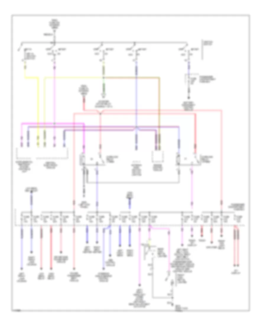
Power Distribution Wiring Diagram (2 of 3) for Volvo V70 T-5 2001
List of elements for Power Distribution Wiring Diagram (2 of 3) for Volvo V70 T-5 2001:
- (diesel only)
- (not used)
- (s80)
- (v70)
- 15a
- A red
- A/c relay
- Accelerator pedal sensor
- Battery disconnect control module
- Battery fuse box
- Brake light relay
- C20
- C23
- C24
- C25
- Canister valve
- Cargo compartment 12v outlet (s80)
- Cargo compartment fuse box
- Cd changer, rti cd-rom player, rti control module, pager alarm
- Electronic throttle module
- Engine compartment relay/fuse box
- Engine control module
- Engine control module main relay
- Engine control module, fuel injectors, mass airflow sensor
- Evap valve, camshaft reset valve, air preheating ptc resistor turbo control valve
- From battery (diagram 1 of 3)
- From f fuse a7 (diagram 1 of 3)
- From fuse d5 (diagram 2 of 3)
- Fuse a8 60a
- Fuse b10 10a
- Fuse b11 20a
- Fuse b20
- Fuse b21
- Fuse b23 5a
- Fuse b3
- Fuse b4 20a
- Fuse b5 15a
- Fuse b6 15a
- Fuse b7 10a
- Fuse b8 10a
- Fuse d1 10a
- Fuse d10 10a
- Fuse d11 15a
- Fuse d12 15a
- Fuse d13 15a
- Fuse d14
- Fuse d15 20a
- Fuse d16
- Fuse d2 10a
- Fuse d3 15a
- Fuse d4 10a
- Fuse d5 5a
- Fuse d6 10a
- Fuse d7 1oa
- Fuse d8 15a
- Fuse d9 15a
- Fuse e1 40a
- Fuse e2 40a
- Fuse e3 40a
- Fuse e4
- Fuse e5 40a
- Fuse e6
- Fuse e7 40a
- G316 (rear of right rear door sill)
- Heated oxygen semsor, engine control module
- Heated rear window relay
- Left/right rear door lock unit, fuel filter flap locking/ unlocking relay
- Nca
- Rear accessory relay (15 feed)
- Rear adjustable head restraint relay (s80), cargo rear shunt 12v outlet (v70)
- Rear electronic module
- Rear electronic module (rem)
- Rear window washer motor relay
- Rear window wiper relay, intermittent rear window wiper on/off relay
- Red
- Reversing light relay
- Spark plug & ignition coil, egr valve, turbo control valve, engine pad solenoid, air preheating ptc resistor
- Sub- woofer
- To rear accessory relay (diagram) 2 of 3
- Towing bracket wiring
- Trunk lid opening relay (s80), tailgate locking relay, tailgate unlock relay
Power Distribution Wiring Diagram (3 of 3) for Volvo V70 T-5 2001
List of elements for Power Distribution Wiring Diagram (3 of 3) for Volvo V70 T-5 2001:
- 15i
- Abs control module
- Acc
- Amplifier
- Antenna ring/ ignition switch lighting
- Battery disconnect control module
- Central electronic module
- Driver side power seat module
- Engine control module
- From fuse a3 (diagram 1 of 3)
- From fuse c25 (diagram 1 of 3)
- Front ciga- rette lighter
- Front fog light relay
- Fuse c1 10a
- Fuse c10 15a
- Fuse c11 15a
- Fuse c12 15a
- Fuse c13 20a
- Fuse c14 5a
- Fuse c15 5a
- Fuse c16 20a
- Fuse c17 30a
- Fuse c18 15a
- Fuse c19 10a
- Fuse c2 10a
- Fuse c20 5a
- Fuse c3 15a
- Fuse c4 20a
- Fuse c5 30a
- Fuse c6 30a
- Fuse c7 15a
- Fuse c8 15a
- Fuse c9 5a
- G200 (left kick panel)
- G203 (right kick panel)
- High beam relay
- Ignition switch
- Key in ignition switch
- Key-in
- Left front lamp housing
- Left hight beam
- Left seat belt lock switch, right seat belt lock switch, passenger side power seat module, center electronic module, srs control module
- Left seat heater
- Left/ right headlight wiper motor, left/right beam adjustment actuator
- Low beam cem, shunt
- Low beam relay
- Nca
- Off
- Overload relay 15-feed
- Overload relay x feed
- Passenger compartment fuse box
- Power passenger seat module
- Radio
- Radio, rti display
- Rear ciga- rette lighter
- Red
- Right front lamp housing
- Right hight beam
- Right seat heater
- Rti display
- Start
- Starter motor relay (diagram 1 of 3)
- Steering angle sensor control module