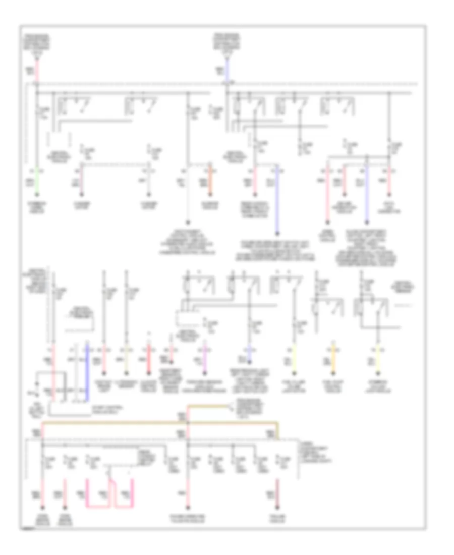
POWER DISTRIBUTION
Power Distribution Wiring Diagram (1 of 3) for Volvo XC60 T-6 2011

List of elements for Power Distribution Wiring Diagram (1 of 3) for Volvo XC60 T-6 2011:
- 74/504b
- Accelerator pedal sensor
- Alternator control module & starter motor
- Auto dimming rearview mirror
- Auxiliary lights relay
- Battery
- Battery fuses
- Brake control module
- Central electronic module
- Central electronic module (behind right end of dash)
- Climate control system relay
- Combustion preheater module & remote parking heater start control module
- Cooling fan control module
- Electronic power steering control module
- Electronic power steering module
- Engine compartment distribution box (left side of engine compt)
- Engine control module
- Engine management system main relay
- Fan control module & passenger compartment fan motor
- Feed relay
- Forward aimed radar
- Forward sensing module
- From a fuse a7 (diagram 1 of 3)
- Fuse a1 50a
- Fuse a2 50a
- Fuse a3 60a
- Fuse a4 60a
- Fuse a43 80a
- Fuse a44 100a
- Fuse a5 60a
- Fuse a6 (not used)
- Fuse a7 100a
- Fuse b10 25a
- Fuse b11 40a
- Fuse b12 (not used)
- Fuse b13 40a
- Fuse b14 20a
- Fuse b16 10a
- Fuse b17 20a
- Fuse b18 5a
- Fuse b19 5a
- Fuse b20 10a
- Fuse b21 10a
- Fuse b23 5a
- Fuse b27 5a
- Fuse b28 20a
- Fuse b29 15a
- Fuse b30 10a
- Fuse b31 15a
- Fuse b32 15a
- Fuse b34 30a
- Fuse b8 20a
- Fuse b9 30a
- Fuse f18 10a
- Fuse f19 5a
- Fuse f20 7.5a
- Fuse pf1 150a
- Fuse pf2 150a
- G3 (left side of engine compt)
- Headlamp control module
- Headlight washer motor relay
- Horn relay
- Left heated windshield washer nozzle & right heated windshield washer nozzle
- Light switch module
- Nca
- Occupant weight sensor
- Ptc element
- Ptc element & heated rear seat switch
- Red
- Starter motor relay
- To cargo compartment fuse box (diagram 2 of 3)
- To central electronic module (diagram 2 of 3)
- To fuse a43 (diagram 1 of 3)
- To passenger compartment distribution box (diagram 3 of 3)
- Transmission control module
- Wiper motor module
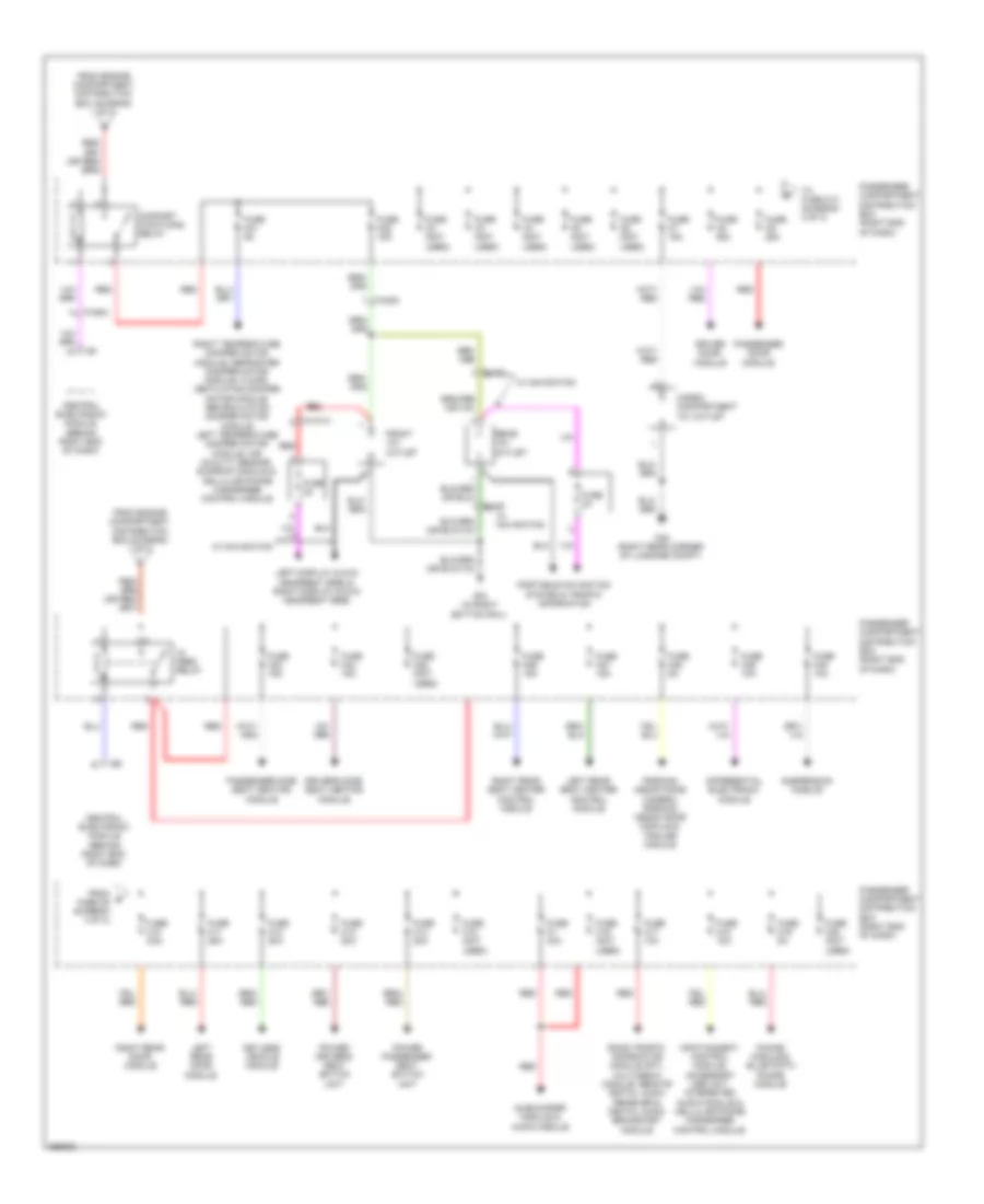
Power Distribution Wiring Diagram (2 of 3) for Volvo XC60 T-6 2011
List of elements for Power Distribution Wiring Diagram (2 of 3) for Volvo XC60 T-6 2011:
- Cargo compartment fuse box (left side of luggage compt)
- Central electronic module
- Central electronic module (behind right end of dash)
- Climate control module
- Contact brake light
- Data link connector
- Driver information module
- Forward sensing module & forward-aimed radar
- From engine compartment distribution box (diagram 1 of 3)
- Fuel filler cover lock motor
- Fuel pump control module
- Fuse a1 30a
- Fuse a11 40a
- Fuse a2 30a
- Fuse a3 30a
- Fuse a4 (not used)
- Fuse a5 30a
- Fuse a6 (not used)
- Fuse a7 (not used)
- Fuse a8 (not used)
- Fuse f1 15a
- Fuse f10 15a
- Fuse f13 20a
- Fuse f14 5a
- Fuse f15 15a
- Fuse f16 5a
- Fuse f21 15a
- Fuse f22 5a
- Fuse f23 20a
- Fuse f24 5a
- Fuse f3 7.5a
- Fuse f4 5a
- Fuse f5 10a
- Fuse f6 7.5a
- Fuse f7 7.5a
- Fuse f8 10a
- Fuse f9 15a
- G83 (in left bottom rail)
- Glove compartment lighting, left front courtesy lighting, right front courtesy lighting, driver's side sill moldings converter/control module & passenger side sill moldings converter/control module
- Heartbeat sensor & front mass movement sensor module
- Infotainment control module, accessory usb unit, integrated audio module, & cellular phone handsfree control module
- Park brake module
- Power driver's seat switch unit, cargo compartment ceiling light, tailgate closing switch, power passenger seat switch unit & driver's door power window switches
- Power operated tailgate module
- Rear reading light, left vanity mirror lighting, right vanity mirror lighting & ceiling light switch unit
- Rear window heated relay
- Rear window wiper relay & rear window wiper motor
- Red
- Siren control module
- Start control module (scu)
- Steering column lock module
- Steering wheel module
- Sunroof module
- Trailer module
- Ultrasonic sensor
- Washer motor
Power Distribution Wiring Diagram (3 of 3) for Volvo XC60 T-6 2011
List of elements for Power Distribution Wiring Diagram (3 of 3) for Volvo XC60 T-6 2011:
- 74/1014
- 74/504
- 74/530
- 9x/25
- Cargo compartment 12v outlet
- Central electronic module (behind right end of dash)
- Comfort functions relay
- Differential electronic module
- Driver door module
- Driver's side seat heating module
- Feed relay
- From engine compartment distribution box (diagram 1 of 3)
- From g fuse c9 (diagram 3 of 3)
- Front 12v outlet
- Fuse 2a
- Fuse c1 40a
- Fuse c10 25a
- Fuse c11 25a
- Fuse c12 20a
- Fuse c13 20a
- Fuse c14 20a
- Fuse c15 (not used)
- Fuse c16 (not used)
- Fuse c17 10a
- Fuse c18 15a
- Fuse c19 5a
- Fuse c2 (not used)
- Fuse c20 (not used)
- Fuse c21 5a
- Fuse c22 15a
- Fuse c23 15a
- Fuse c24 15a
- Fuse c25 (not used)
- Fuse c26 15a
- Fuse c27 15a
- Fuse c28 5a
- Fuse c29 10a
- Fuse c3 (not used)
- Fuse c30 10a
- Fuse c4 (not used)
- Fuse c5 (not used)
- Fuse c6 (not used)
- Fuse c7 15a
- Fuse c8 25a
- Fuse c9 25a
- G15 (in right bottom rail)
- G48 (right rear corner of luggage compt)
- Infotainment control module, accessory usb unit, integrated audio module & cellular phone handsfree control module
- Keyless vehicle module
- Left display & dvd headrest (rse) & right display & dvd headrest (rse)
- Left rear door module
- Left rear seat heater control module
- Parking assistance camera, parking assistance module & trailer module
- Passenger compartment distribution box (right end of dash)
- Passenger door module
- Passenger side seat heating module
- Portable navigation system & traffic information
- Power driver's seat switch unit
- Power passenger seat switch unit
- Rear 12v outlet
- Red
- Right rear door module
- Right rear seat heater control module
- Right temperature damper motor module, defroster damper motor module, floor/ ventilation damper motor module, recirculation damper motor module, left temperature damper motor module, air quality sensor, sunroof module & cellular phone handsfree control module
- Road traffic information module (rti), multimedia module, remote digital audio receiver & digital audio broadcast module
- Subwoofer module & audio module
- Suspension module
- To fuse c10 (diagram 3 of 3)
- W/ navigation