POWER DISTRIBUTION
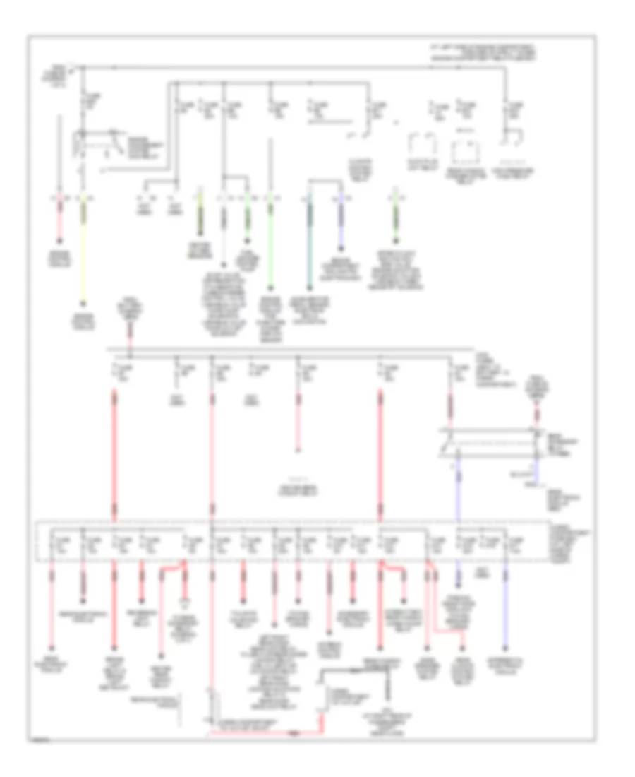
Power Distribution Wiring Diagram (1 of 3) for Volvo XC90 2004

List of elements for Power Distribution Wiring Diagram (1 of 3) for Volvo XC90 2004:
- (at left end of dash) passenger compartment relay/fuse box
- (at left side of engine compt, forward of strut tower) engine compartment relay/fuse box
- (not used)
- Accessory (auxiliary light)
- Battery
- Brake control module (bcm)
- Brake light contact
- Capacitor
- Central electronic module
- Combustion preheater module (cpm)
- Cooling fan control module & electric cooling fan motor
- Data link connector, light switch module. climate control module & steering wheel module
- Extended d1 feed relay
- Extended d2 feed relay & gear selector module
- Fan control module
- From ignition switch (diagram 3 of 3)
- From overload relays (diagram 3 of 3)
- Front fog light relay
- Fuel pump relay
- Fuse a2 60a
- Fuse a3 60a
- Fuse a4 60a
- Fuse a8 80a
- Fuse b1 25a
- Fuse b12 5a
- Fuse b13 25a
- Fuse b14 30a
- Fuse b16 15a
- Fuse b19 30a
- Fuse b2 20a
- Fuse b22 25a
- Fuse b9 15a
- Fuse c1 30a
- Fuse c20 10a
- Fuse c21 10a
- Fuse c22 5a
- Fuse c23 20a
- Fuse c24 10a
- Fuse c25 15a
- Fuse c26 15a
- Fuse c27 10a
- Fuse c28 5a
- Fuse c32 7.5a
- Fuse c33 7.5a
- Fuse c34 15a
- Fuse c35
- Fuse c36 20a
- Fuse c37 10a
- Fuse c38 15a
- G93 (at rear of left fender)
- Generator
- High beam relay
- Horn relay
- Infotainment relay
- Intermittent windshield wiper relay
- Jump start terminal
- Left front position/ parking light, towing bracket module & tail light/ parking light/ position light rem shunt
- Left/right cem indicator shunt &
- Low beam/ bl-xenon relay & daytime running lights relay
- Low/high speed windshield wiper relay
- Multimedia display, md control module, cd control module & infotainment accessory wiring
- Parking/position lights relay (in passenger compartment relay box)
- Red
- Right front position/ parking light, position light/ parking light/tail light rem shunt, license plate lights & towing bracket wiring
- Siren control module
- Starter motor
- Starter motor relay
- Sunroof control module
- To battery fuse box (diagram 2 of 3)
- To fuse b23 (diagram 2 of 3)
- To fuse c1 (diagram 3 of 3)
- To fuse c3 (diagram 3 of 3)
- To fuse c5 (diagram 3 of 3)
- Windshield washer motor relay
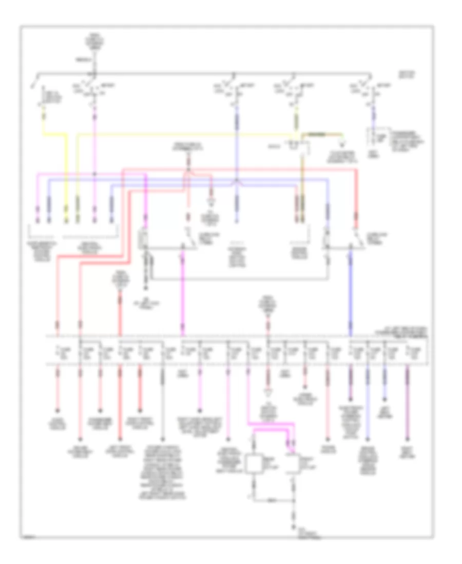
Power Distribution Wiring Diagram (2 of 3) for Volvo XC90 2004
List of elements for Power Distribution Wiring Diagram (2 of 3) for Volvo XC90 2004:
- (at left side of engine compartment, forward of strut tower) engine compartment relay/fuse box
- (not used)
- A red
- Accelerator pedal sensor, electrics box & cooling fan
- Accessory electronic module
- Antenna control module
- Bass speaker system relay
- Brake light relay & brake light rem shunt
- Cargo compartment 12v outlet
- Cargo compartment 12v outlet shunt
- Cargo compartment fuse box (at left side of cargo compt)
- Climate control system relay
- D18
- Differential electronic module
- Engine compartment cooling fan electrics box
- Engine control module
- Engine control module, fuel injectors & mass airflow sensor
- Engine management system main relay
- Evap valve, air preheating ptc resistor, turbocharger control valve, variable valve timing inlet solenoid & variable valve timing outlet solenoid
- From b fuse b2 (diagram 1 of 3)
- From battery (diagram 1 of 3)
- From fuse d5 (diagram 2 of 3)
- Fuel leakage control pump
- Fuse a1 60a
- Fuse b10 10a
- Fuse b11 20a
- Fuse b15 25a
- Fuse b23 5a
- Fuse b3
- Fuse b4 20a
- Fuse b5 10a
- Fuse b6 15a
- Fuse b8 10a
- Fuse d1 10a
- Fuse d10 5a
- Fuse d11 15a
- Fuse d12 15a
- Fuse d13 15a
- Fuse d15 20a
- Fuse d16
- Fuse d17 7.5a
- Fuse d2 10a
- Fuse d3 15a
- Fuse d4 10a
- Fuse d5 5a
- Fuse d6 10a
- Fuse d7 15a
- Fuse d8 20a
- Fuse d9 15a
- Fuse e1 40a
- Fuse e2 40a
- Fuse e3 40a
- Fuse e4
- Fuse e5 40a
- Fuse e6
- Fuse e7 40a
- G73 (at right rear of passenger's compt, near floor)
- Glow plug unit relay
- Heated oxygen sensors
- Heated rear window relay
- High pressure wash relay
- Intermittent rear window wiper on/off relay
- Left/right rear door deadlock relay, filler flap/rear doors locking relay, fuel filler flap unlocking relay, left/right rear door locking/unlocking relay & rear door deadlock relay
- Main fuses (next to battery, in cargo compartment)
- Parking assistance module & towing bracket wiring
- Rear accessory relay (15 feed)
- Rear climate control system relay
- Rear electrical module
- Rear electronic module
- Rear electronic module (rem)
- Rear window washer motor relay
- Rear window wiper relay
- Red
- Reversing light relay
- Spark plug & ignition coil, egr valve, engine mounting solenoid valve & variable turbo geometry solenoid
- Tailgate unlocking relay
- To rear accessory relay (diagram) 2 of 3
- Towing bracket wiring
Power Distribution Wiring Diagram (3 of 3) for Volvo XC90 2004
List of elements for Power Distribution Wiring Diagram (3 of 3) for Volvo XC90 2004:
- (at left end of dash) passenger compartment relay/ fuse box
- (not used)
- 15i
- 54/3lc
- Acc
- Antenna ring/ ignition switch lighting
- Audio control module
- Brake control module & steering angle sensor module
- Central electronic module
- Central electronic module & passenger power seat module
- Driver power seat module
- Electronic power steering control module & vacuum pump switch
- Engine control module
- From fuse a2 (diagram 1 of 3)
- From fuse a3 (diagram 1 of 3)
- From fuse a4 (diagram 1 of 3)
- From fuse c12 (diagram 1 of 3)
- Front 12v outlet
- Fuse c10 5a
- Fuse c11 15a
- Fuse c12 10a
- Fuse c13
- Fuse c14 10a
- Fuse c15 10a
- Fuse c16 15a
- Fuse c17 5a
- Fuse c18 15a
- Fuse c19 15a
- Fuse c2 30a
- Fuse c29
- Fuse c3 30a
- Fuse c4 30a
- Fuse c5 25a
- Fuse c6 25a
- Fuse c7 30a
- Fuse c8
- Fuse c9 15a
- G10 (at right kick panel)
- G6 (at left kick panel)
- Ignition switch
- Key in ignition switch
- Left front door control module
- Left seat heater
- Lock
- Nca
- Off
- Off on
- Overload relay 15-feed
- Overload relay x feed
- Passenger compartment relay/fuse box (at left end of dash)
- Passenger power seat module
- Phone module
- Power window/ power child lock rear door relay,
- Rear 12v outlet
- Red
- Right front door control module
- Right hand headlight adjustment motor & left hand headlight level adjustment motor
- Right rear power window up relay, right rear power window down relay, rear power window down relay, rear power window up relay & left/right rear door power window switch
- Right seat heater
- Start
- To fuse c34 (diagram 1 of 3)
- To ignition switch (diagram 3 of 3)
- To starter motor relay (diagram 1 of 3)
- Upper electronic module