POWER DISTRIBUTION
Power Distribution Wiring Diagram (1 of 2) for Volvo XC90 2011

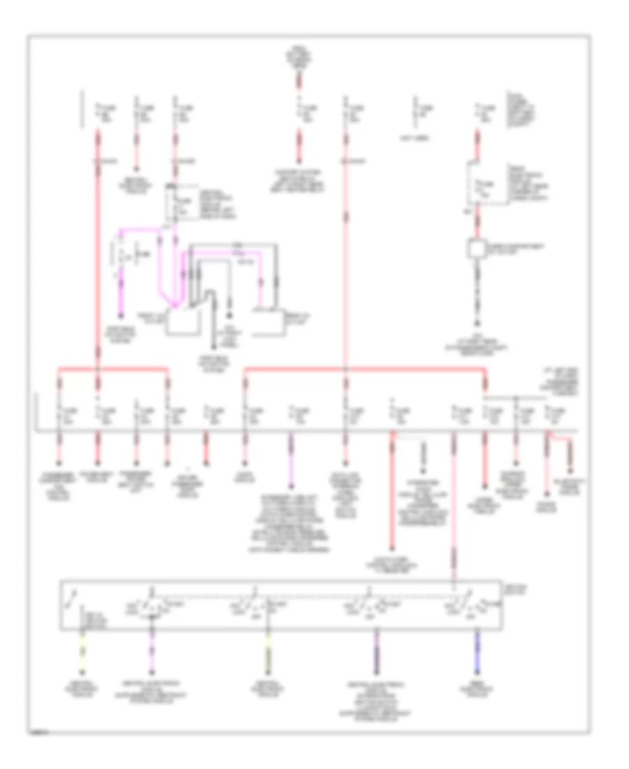
List of elements for Power Distribution Wiring Diagram (1 of 2) for Volvo XC90 2011:
- & variable valve
- (4.4l)
- (4.4l),
- (4.4l), (4.4l),
- (left side of engine compt)
- (not used)
- 3.2l
- 4.4l
- Alternator control module
- Auxiliary light relay
- Battery
- Brake control module
- Central electronic module
- Climate control system relay, accelerator pedal sensor
- Climate control system, front & rear cam profile solenoids, engine control module, variable valve timing intake bank 2 variable valve timing exhaust bank 2 solenoid variable valve timing exhaust bank 1 solenoid
- Combustion preheater module
- Cooling fan control module
- Electromagnetic clutch,
- Engine compartment distribution box (left side of engine compt)
- Engine control module
- Engine control module, injectors & mass airflow sensor
- Engine control module, intake manifold upper actuating motor & intake manifold lower actuating motor
- Engine management system main relay
- Evap valve, mass air flow sensor, fuel leakage control pump, variable valve timing intake bank 1
- Front & rear heated oxygen sensor banks
- Fuse a1
- Fuse a2 60a
- Fuse a3
- Fuse a4
- Fuse a5
- Fuse b1 30a
- Fuse b10 20a
- Fuse b11 10a
- Fuse b12 15a
- Fuse b13 10a
- Fuse b14 20a
- Fuse b15 15a
- Fuse b16 20a
- Fuse b17 20a
- Fuse b19 5a
- Fuse b2 30a
- Fuse b20 15a
- Fuse b21 20a
- Fuse b3 35a
- Fuse b4 25a
- Fuse b5 20a
- Fuse b6 35a
- Fuse b7 25a
- Fuse b8 15a
- Fuse b9 15a
- G53
- High pressure headlight washer motor relay
- Intermittent wiping relay
- Jump start connection
- Nca
- Red
- Solenoid
- Spark plug condenser & ignition coils
- Starter motor
- Starter motor relay
- Timing intake solenoid
- To main fuses (diagram 2 of 2)
- Transmission control module
- Vacuum pump relay
- Variable intake valve
Power Distribution Wiring Diagram (2 of 2) for Volvo XC90 2011
List of elements for Power Distribution Wiring Diagram (2 of 2) for Volvo XC90 2011:
- (at left end of dash) passenger compartment fuse box
- (not used)
- 54/134
- 54/40c
- 54/40d
- A red
- A17
- Acc
- Accessory usb unit, multimedia display, multimedia module, dvd player/control module, cellular phone handsfree relay, satellite radio receiver, cellular phone handsfree control module, infotainment cable harness
- Audio module
- B31
- Cargo compartment 12v outlet
- Central electronic module
- Central electronic module (behind left side of dash)
- Comfort system seats relay, left & right rear seat heater relay
- Data link connector, steering wheel module & light switch module
- Driver/ passenger door module
- Dvd player/ control module & tv receiver
- From battery (diagram 1 of 2)
- Front 12v outlet
- Fuse
- Fuse 15a
- Fuse c1 30a
- Fuse c10 5a
- Fuse c11 7.5a
- Fuse c12 10a
- Fuse c13 15a
- Fuse c14 5a
- Fuse c2 30a
- Fuse c3 25a
- Fuse c4 25a
- Fuse c5 25a
- Fuse c6 25a
- Fuse c8 15a
- Fuse c9 10a
- Fuse e1 60a
- Fuse e2
- Fuse e3 40a
- Fuse e4 50a
- Fuse e5 50a
- Fuse e6 50a
- Fuse e7 50a
- G10 (at right kick panel)
- G73 (at right rear of passenger's compt, near floor)
- Ignition switch
- Integrated audio module, cellular phone handsfree control module & cellular phone handsfree relay
- Key in ignition switch
- Lock
- Main fuses (next to battery, in cargo compt)
- Off
- Passenger compartment fan control module
- Passenger power seat switch unit
- Phone module
- Portable navigation system
- Power seat module
- Rear 12v outlet
- Rear electronic module
- Rear electronic module (at left rear corner of cargo compt)
- Red
- Start
- Sunroof module & upper electronic module
- Upper electronic module