POWER DISTRIBUTION
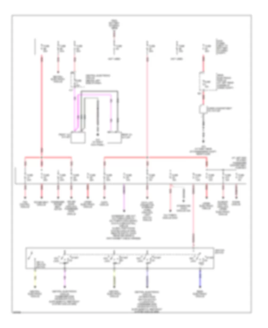
Power Distribution Wiring Diagram (1 of 2) for Volvo XC90 V8 2008

List of elements for Power Distribution Wiring Diagram (1 of 2) for Volvo XC90 V8 2008:
- (left side of engine compt)
- (not used)
- Accelerator pedal sensor & engine compartment electrics box cooling fan
- Alternator control module
- Auxiliary light relay (accessory)
- Battery
- Brake control module
- Central electronic module
- Climate control system relay
- Combustion preheater module
- Condensor & ignition coils
- Cooling fan control module
- Engine compartment distribution box (left side of engine compt)
- Engine control module
- Engine control module, injectors & mass airflow sensor
- Engine management system main relay
- Evap valve, mass air flow sensor, fuel pump leakage control, variable valve timing intake bank 1, electromagnetic clutch, climate control system, engine control module, variable valve timing intake bank 2, variable valve timing exhaust bank 2, variable valve timing exhaust bank 1 & variable intake valve
- Front & rear heated oxygen sensor banks
- Fuse a1
- Fuse a2 60a
- Fuse a3
- Fuse a4
- Fuse a5
- Fuse b1 30a
- Fuse b10 20a
- Fuse b11 10a
- Fuse b12 15a
- Fuse b13 10a
- Fuse b14 20a
- Fuse b15 15a
- Fuse b16 20a
- Fuse b17 20a
- Fuse b19 5a
- Fuse b2 30a
- Fuse b20 15a
- Fuse b21
- Fuse b3 35a
- Fuse b4 25a
- Fuse b5 20a
- Fuse b6 35a
- Fuse b7 25a
- Fuse b8 15a
- Fuse b9 15a
- G53
- High pressure headlight washer motor relay
- Intermittent wiping relay
- Jump start terminal
- Nca
- Red
- Spark plug,
- Starter motor
- Starter motor relay
- To main fuses (diagram 2 of 2)
- Transmission control module
Power Distribution Wiring Diagram (2 of 2) for Volvo XC90 V8 2008
List of elements for Power Distribution Wiring Diagram (2 of 2) for Volvo XC90 V8 2008:
- (at left end of dash) passenger compartment fuse box
- (not used)
- (suspension module)
- A red
- A17
- Acc
- Accessory usb unit, multimedia display, multimedia module(mmm), dvd player/control module, global positioning system module (gps), remote digital audio receiver (rdar) & infotainment cable harness
- Audio module
- B31
- Cargo compartment 12v outlet
- Central electronic module
- Central electronic module (behind left side of dash)
- Data link connector, steering wheel module & light switch module
- Driver door module & passenger door module
- Fan control module
- From battery (diagram 1 of 2)
- Front 12v outlet
- Fuse 15a
- Fuse c1 30a
- Fuse c10 5a
- Fuse c11 7.5a
- Fuse c12 10a
- Fuse c13 15a
- Fuse c14 5a
- Fuse c2 30a
- Fuse c3 25a
- Fuse c4 25a
- Fuse c5 25a
- Fuse c6 25a
- Fuse c8 15a
- Fuse c9 10a
- Fuse e1 60a
- Fuse e2 40a
- Fuse e3
- Fuse e4 50a
- Fuse e5 50a
- Fuse e6 50a
- Fuse e7 50a
- G10 (at right kick panel)
- G73 (at right rear of passenger's compt, near floor)
- Ignition switch
- Integrated audio module (iam)
- Key in ignition switch
- Lock
- Main fuses (next to battery, in cargo compt)
- Multimedia module (mmm)
- Off
- Passenger power seat motor
- Phone module
- Power seat module
- Rear 12v outlet
- Rear electronic module
- Rear electronic module (at left rear corner of cargo compt)
- Red
- Start
- Sunroof control module & upper electronic module
- Upper electronic module