POWER DOOR LOCKS
Power Door Locks Wiring Diagram for Ford Explorer 2004
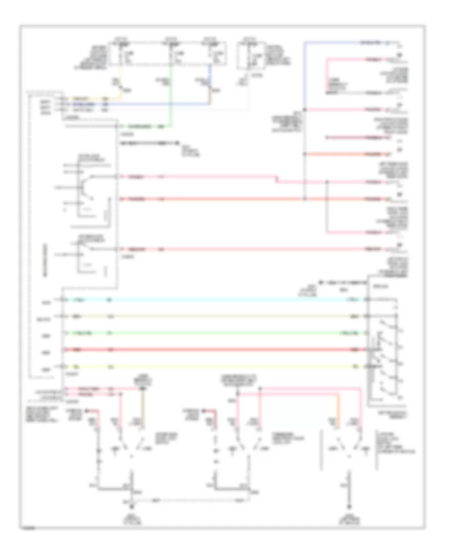
List of elements for Power Door Locks Wiring Diagram for Ford Explorer 2004:
- (near breakout to c3134) s315
- (near breakout to c3134) s318
- (near breakout to driver safety belt buckle switch)
- 1/2
- 3/4
- 5/6
- 7/8
- 9/0
- Battery junction box (bjb) (left side of engine compt, at fender apron)
- C270e
- C3203d
- C3203e
- C3203f
- Central junction box (cjb) (behind left side of dash)
- Door lock/ unlock relay
- Driver door unlock relay
- Driver side door lock switch
- Fuse 15a
- Fuse 20a
- Fuse 30a
- Fuse 5a
- G400 (left rear of vehicle)
- G401 (at right "d" pillar)
- G401 (at right ``d" pillar)
- Ground
- Hot at all times
- Interior lights system
- Key pad switch assembly
- Left front door lock actuator (at rear of left front door)
- Left rear door lock actuator (at rear of left rear door)
- Liftgate door lock switch (at left rear corner of vehicle)
- Liftgate lock actuator (on center of liftgate)
- Lock
- Lock relay
- Microprocessor
- Passenger side front door lock unit
- Pwr
- Red
- Right front door lock actuator (at rear of right front door)
- Right rear door lock actuator (at rear of right rear door)
- S205
- S259
- S308
- S312 (near breakout to passenger's safety belt buckle switch)
- S502
- S602
- Sig rtn
- Unlk
- Unlock relay
- Vbatt
- Vehicle security module (vsm) (above right rear wheelwell)
- Vpwr
- Vref
 Русский