POWER DOOR LOCKS
Power Door Locks Wiring Diagram, with Keyless Entry for Toyota Celica GT 2004

List of elements for Power Door Locks Wiring Diagram, with Keyless Entry for Toyota Celica GT 2004:
- Acc
- Act+
- Act-
- Actd
- Back door lock motor (on rear of liftback)
- Body ecu
- Body ecu-ig fuse 5a
- C12
- C13
- Combination meter
- Dcty
- Door control receiver (behind trim panel, above left rear fenderwell)
- Door fuse 20a
- Door lock control switch (power window master switch)
- Ecu-acc fuse 7.5a
- Engine control module (ecm) (on left side of engine compt, forward of battery)
- Gnd
- Gts
- Horn
- Horns system
- Hot at all times
- Hot in acc or on
- Hot in on or start
- I12
- If (at right dash brace)
- Instrument panel j/b (behind panel on right side of center console)
- Interior lights system
- Junction connector 10 (under right side of dash, on center of door pillar)
- Junction connector 11 (in left door)
- Junction connector 14 (on rear of left rear fenderwell)
- Junction connector 3 (under left side of dash, behind kick panel)
- Ksw
- Left door courtesy switch (base of left "b" pillar)
- Left door lock motor, door lock detection switch & door key lock & unlock switch (in left door)
- Lgcy
- Lock
- Lswd
- Lswp
- Mpx+
- Mpx-
- Mpx-b fuse 7.5a
- Mpx1
- Mpx2
- Pcty
- Prg
- Rda
- Red
- Right door courtesy switch (lower right "b" pillar)
- Right door lock motor, door lock detection switch & door key lock & unlock switch (in right door)
- Sg1
- Tx+
- Ul1
- Ul2
- Ul3
- Unlk
- Unlock warning switch (under left side of dash)
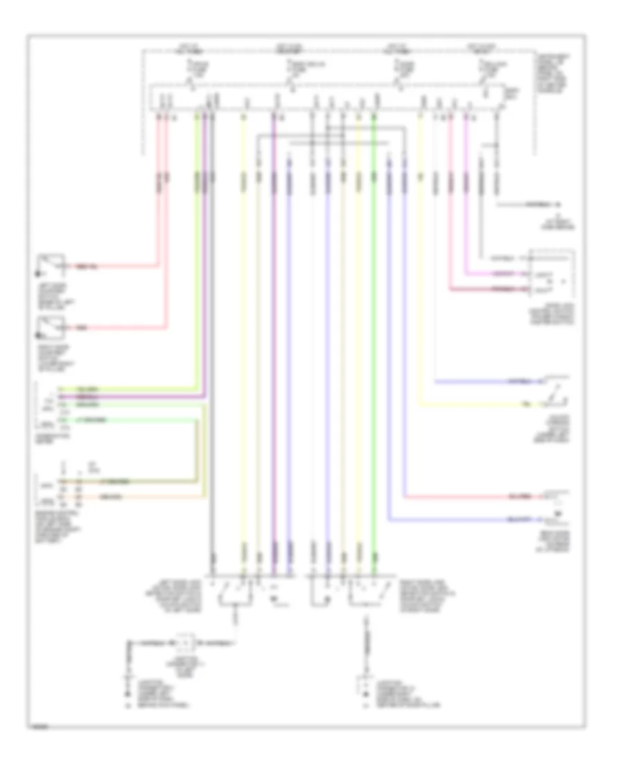
Power Door Locks Wiring Diagram, without Keyless Entry for Toyota Celica GT 2004
List of elements for Power Door Locks Wiring Diagram, without Keyless Entry for Toyota Celica GT 2004:
- Acc
- Act+
- Act-
- Actd
- Back door lock motor (on rear of liftback)
- Body ecu
- Body ecu-ig fuse 5a
- C12
- C13
- Combination meter
- Dcty
- Door fuse 20a
- Door lock control switch (power window master switch)
- Ecu-acc fuse 7.5a
- Engine control module (ecm) (on left side of engine compt, forward of battery)
- Gt gts
- Hot at all times
- Hot in acc or on
- Hot in on or start
- I12
- If (at right dash brace)
- Instrument panel j/b (behind panel on right side of center console)
- Junction connector 10 (under right side of dash, on center of door pillar)
- Junction connector 11 (in left door)
- Junction connector 3 (under left side of dash, behind kick panel)
- Ksw
- Left door courtesy switch (base of left "b" pillar)
- Left door lock motor, door lock detection switch & door key lock & unlock switch (in left door)
- Lock
- Lswd
- Lswp
- Mpx+
- Mpx-
- Mpx-b fuse 7.5a
- Mpx1
- Mpx2
- Pcty
- Red
- Right door courtesy switch (lower right "b" pillar)
- Right door lock motor, door lock detection switch & door key lock & unlock switch (in right door)
- Sg1
- Tx+
- Ul1
- Ul2
- Ul3
- Unlk
- Unlock warning switch (under left side of dash)