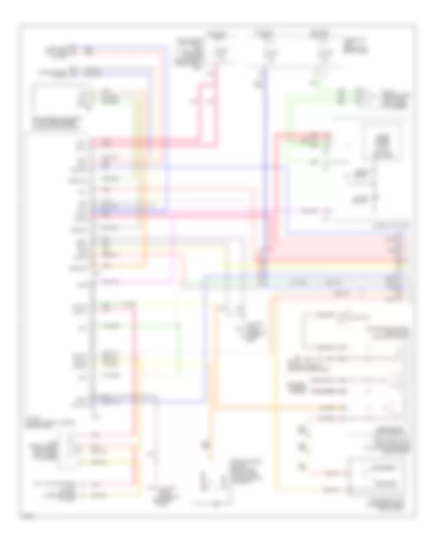
CRUISE CONTROL
Cruise Control Wiring Diagram for Infiniti M45 2004
 https://portal-diagnostov.com/license.html
Automotive Electricians Portal FZCO
Automotive Electricians Portal FZCO
https://portal-diagnostov.com/license.html
https://portal-diagnostov.com/license.html
Automotive Electricians Portal FZCO
Automotive Electricians Portal FZCO
List of elements for Cruise Control Wiring Diagram for Infiniti M45 2004:
- 14r
- 15r
- 21r
- 24r
- 29r
- 31r
- A solenoid monitor input
- Actr output high side
- Air valve
- Air valve output low side
- Ascd
- Ascd brake switch (on bracket, above brake pedal)
- Ascd control unit (behind dash, left of steering column)
- Ascd pump (at right rear corner of engine compartment)
- Ascd steering switch
- Brake nc sw input
- Brake no sw input
- Cancel switch
- Combination meter
- Combination switch (spiral cable)
- Control sw ad input
- Control sw gnd input
- Cruise (green)
- Cruise lamp output
- Data link connector (partial) (under left side
- Depre- ssed
- Depressed
- E24 (at right side of engine compartment)
- Ecm prun input
- Engine control module (behind glove box)
- Etc prun
- F101
- F102
- F104
- F8 (at left front of engine, near oil level gauge)
- Fuse 10a
- Fuse 15a
- Fuse block (j/b) 1 (behind left end of dash)
- Fuse, fusible link & relay block (j/b) (at right side of engine compartment)
- Gnd
- Gnd-c
- Hot at all times
- Hot in on or start
- Ign sw
- J/c 10 (behind upper left end of dash, taped to harness)
- J/c 16 (behind upper right side of dash, taped to harness)
- J/c 5 (behind upper left side of dash, taped to harness)
- J/c 7 (behind upper left side of dash, taped to harness)
- J/c 8 (behind lower left side of dash, taped to harness)
- M25 (behind left side of dash)
- M41
- M42
- M441
- M53
- Main (cruise) switch
- Od cancel signal
- Of dash)
- Off
- Park/neutral position relay
- Pnk
- Release valve
- Release valve out low side
- Released
- Resume/ accel switch
- Rxi
- Set
- Set lamp output
- Set/ coast switch
- Start rly
- Starting/ charging system
- Stoplight switch (on bracket, above brake pedal)
- Tcs input
- Throttle position input
- Transmission control module (tcm) (behind glove box)
- Tvoo
- Txi
- Unified meter control unit
- Vacuum motor
- Vacuum mtr out low side
- Vdc/tcs/abs control unit (behind right kick panel)
- Vehicle speed input
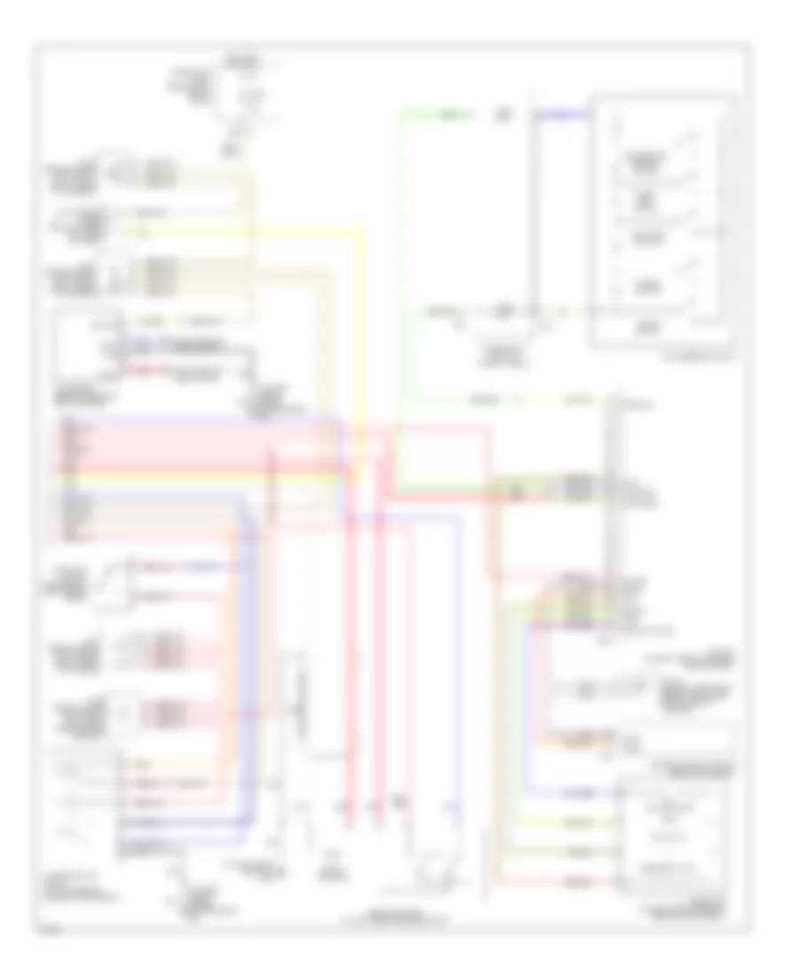
Intelligent Cruise Control Wiring Diagram (1 of 2) for Infiniti M45 2004
List of elements for Intelligent Cruise Control Wiring Diagram (1 of 2) for Infiniti M45 2004:
- 14r
- 15r
- 21r
- 24r
- 29r
- 31r
- B243
- B244
- Bat-1
- Bat-2
- Bnc-sw
- Bno-sw
- Brake pressure sensor (at left rear corner of engine compartment)
- Buzz
- Can-h
- Can-l
- Combination meter
- Computer data lines system
- Corner of trunk) b257
- Cruise (green)
- Data link connector (dlc) (partial) (under left side of dash)
- Ddl-rx
- Ddl-tx
- Depressed
- E24 (at right side of engine compartment)
- F104
- Fuse 10a
- Fuse 15a
- Fuse block (j/b) 1 (behind left end of dash)
- Fuse, fusible link & relay block (j/b) (at right side of engine compartment)
- Fuse, fusible link & relay box (at right side of engine compartment, in engine room box)
- Gnd
- Gnd-1
- Gnd-2
- Gnd-3
- Hot at all times
- Hot in on or start
- Icc brake switch (on bracket, above brake pedal)
- Icc unit (on right side of luggage compartment)
- Ign-1
- Ign-2
- J/c 10 (behind upper left end of dash, taped to harness)
- J/c 8 (behind lower left side of dash, taped to harness)
- M41
- M42
- Park/neutral position relay
- Parking brake switch (behind left side of dash, at park brake assembly)
- Pkb sw
- Pnk
- Psen-gnd
- Psen-pwr
- Psen-sig
- Red
- Released
- Rls-nc
- Rls-no
- Rls-pwr
- Sol+
- Sol-
- Start rly
- Starting/ charging system
- Stp-lmp
- Transmission control module (tcm) (behind glove box)
- Unified meter control unit (with icc indicator)
- Vout
- Vpwr
- Warn
- Wip-h
- Wip-l
- Wiper/washer system
Intelligent Cruise Control Wiring Diagram (2 of 2) for Infiniti M45 2004
List of elements for Intelligent Cruise Control Wiring Diagram (2 of 2) for Infiniti M45 2004:
- (at right front door sill) b217
- (at right side of engine compartment) e24
- 19b
- Accelerate/ resume switch
- Air valve
- Ascd pump (at right rear corner of engine compartment)
- B245
- Boost solenoid
- Brake booster (at left rear of engine compt)
- Can-h
- Can-l
- Cancel switch
- Coast/ set switch
- Combination switch (spiral cable)
- Computer data lines system
- Cruise
- Distance switch
- Engine control module (behind glove box)
- F102
- Fuse 10a
- Fuse block (j/b) 1 (behind left end of dash)
- Gnd
- Gnd-a
- Gnd-s
- Hot in on or start
- Icc brake hold relay (at left rear of engine compartment)
- Icc sensor (behind center of front bumper)
- Icc steering switch
- Icc unit (on right side of luggage compartment)
- Icc warning chime (below lower left side of dash)
- Ignition
- J/c 1 (behind upper left end of dash, taped to harness)
- J/c 25 (behind lower left side of dash, near pass-through grommet)
- J/c 3 (behind upper left end of dash, taped to harness)
- J/c 30 (behind upper right side of dash, near pass-through grommet)
- J/c 7 (behind upper left side of dash, taped to harness)
- M441
- M53
- Nca
- Od-cancel
- On/off switch
- Pnk
- Red
- Release valve
- Safety
- Stoplight switch (on bracket, above brake pedal)
- Strg gnd
- Strg sig
- T-rly
- Tvo
- Tvoo
- Vacuum motor
- Vent

 Čeština
 Dansk
Dansk Deutsch
 Ελληνικά
 English
 English
 Español
 Suomi
Suomi Français
 Français
 עברית
עברית Hrvatski
 Magyar
 Italiano
 日本語
日本語 한국어
한국어 Nederlands
 Polski
 Português
 Română
 Русский
 Slovenčina
 Slovenščina
 Svenska
 Türkçe
 中文 (中国)