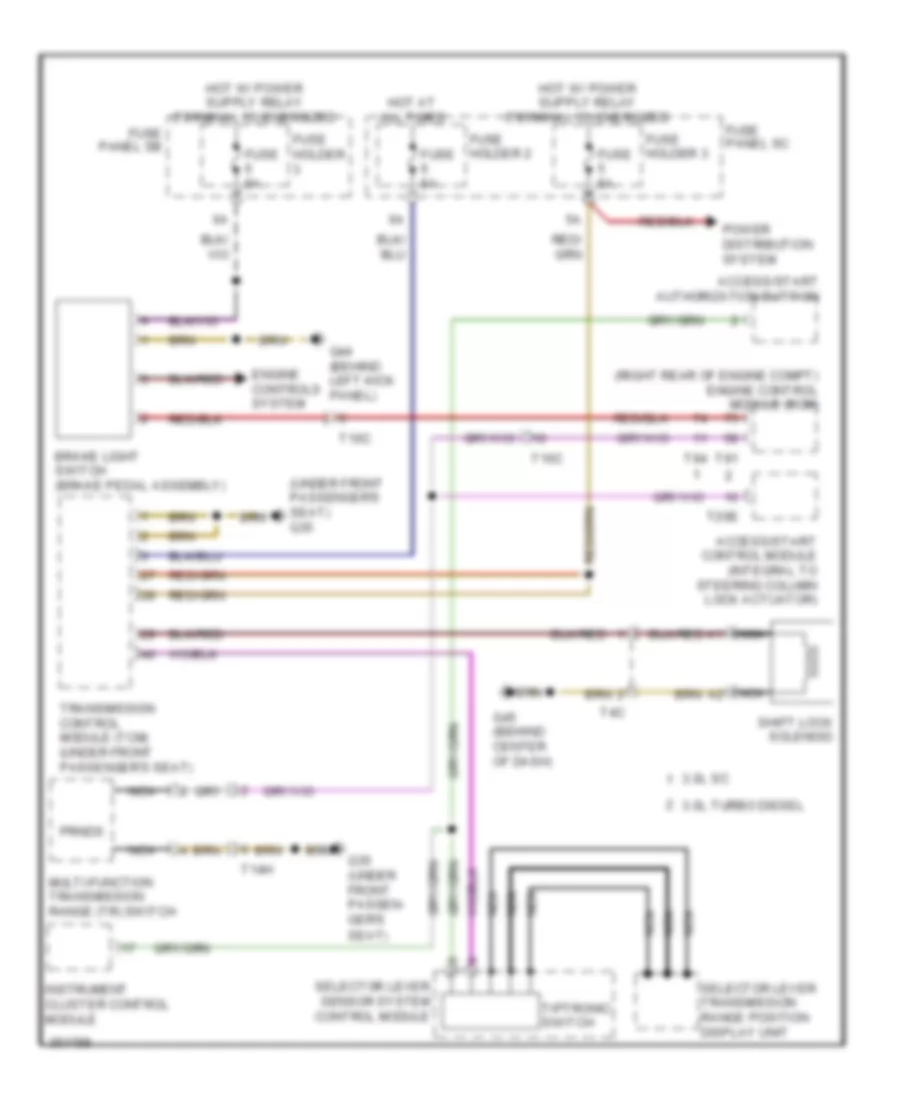
SHIFT INTERLOCK
Shift Interlock Wiring Diagram for Audi Q7 3.0 TDI 2011
List of elements for Shift Interlock Wiring Diagram for Audi Q7 3.0 TDI 2011:
- (right rear of engine compt) engine control module (ecm)
- (under front passenger's seat) g35
- 3.0l sc
- 3.0l turbo diesel
- Access/start authorization buttion
- Access/start control module (integral to steering column lock actuator)
- Brake light switch (brake pedal assembly)
- Engine controls system
- Fuse 5a
- Fuse holder
- Fuse holder 2
- Fuse holder 3
- Fuse panel sb
- Fuse panel sc
- G35 (under front passen- ger's
- G44 (behind left kick panel)
- G45 (behind center of dash)
- Hot at all times
- Instrument cluster control module
- Multi-function transmission range (tr) switch
- Nca
- Power distribution system
- Prnds
- Seat)
- Selector lever sensor system control module
- Selector lever transmission range position display unit
- Shift lock solenoid
- T10c
- T14h
- T20e
- T4c
- T91
- T94
- Tiptronic switch
- Transmission control module (tcm) (under front passenger's seat)
 Čeština
 Dansk
Dansk Deutsch
 Ελληνικά
 English
 English
 Español
 Suomi
Suomi Français
 Français
 עברית
עברית Hrvatski
 Magyar
 Italiano
 日本語
日本語 한국어
한국어 Nederlands
 Polski
 Português
 Română
 Русский
 Slovenčina
 Slovenščina
 Svenska
 Türkçe
 中文 (中国)
 Português