ELECTRONIC SUSPENSION
Electronic Suspension Wiring Diagram (1 of 2) for Ford Explorer 1996


List of elements for Electronic Suspension Wiring Diagram (1 of 2) for Ford Explorer 1996:
- (left rear corner of engine compartment, on fender apron)
- 4x4 high sig
- 4x4 low sig
- Arc accel sig
- Arc compr rly
- Arc off/on sw
- Automatic ride control (arc) module (left center of i/p)
- Automatic ride control compressor assembly (at rear of vehicle)
- Automatic ride control off/on switch (rear of vehicle)
- Automatic ride control relay
- Auxiliary relay box #3 (left rear of engine compartment)
- Brake on/off sw
- C2000
- C2001
- Comp vent sol
- Door ajar in
- Engine controls system
- Front fill sol
- Frt & rr gate sol
- Fuse 18 15a
- Fuse 3 50a
- G100 (w/o cellular phone) (left rear corner of engine compt.)
- G104
- G104 (left rear corner of engine compt, at fender apron)
- G105 (right side of engine compt)
- G1oo (left front of engine compt, near radiator)
- G200 (left kick panel)
- G201 (w/ cellular phone) (right side of i/p)
- Gnd
- Height sen power
- Hot at all times
- Iso link
- Left front shock actuator (at left front shock)
- Left rear shock actuator (at left rear shock)
- Lf height sen
- Lf shock actuator
- Lf shock pos fb
- Lr shock actuator
- Lr shock pos fb
- Nca
- Pcm accel sig
- Pnk
- Power (hot in run)
- Power distribution box
- Powertrain control module (pcm) (right rear of engine compt.)
- Rear fill sol
- Rear height sen
- Red
- Rf shock actuator
- Rf shock pos fb
- Right front shock actuator (at right front shock)
- Right rear shock actuator (at right rear shock)
- Rr shock actuator
- Rr shock pos fb
- Steering sen a
- Steering sen b
- Steering sensor (in steering column)
- Vehicle speed sensor (on transmission)
- Vss (+)
- Warning sig
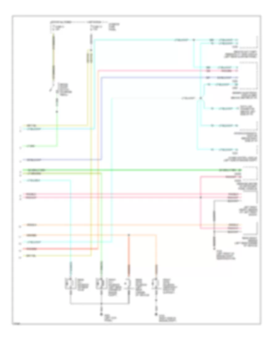
Electronic Suspension Wiring Diagram (2 of 2) for Ford Explorer 1996
List of elements for Electronic Suspension Wiring Diagram (2 of 2) for Ford Explorer 1996:
- 4wabs control module (left side of engine compt)
- Air bag diagnostic monitor (behind right side of i/p)
- Brake on/off switch (on brake pedal)
- C2008
- C2009
- C233
- C280
- C282
- C336
- Data link connector (behind left side of i/p)
- Front fill solenoid (left rear corner of engine compt)
- Front gate solenoid (near right radiator support)
- Fuse 13 15a
- Fuse 1o 7.5a
- G100 (left front of engine compt, near radiator)
- G105 (right side of engine compt)
- G200 (left kick panel)
- Generic electronic module (gem) (behind center of i/p)
- Hot at all times
- Hot in run
- Interior fuse panel
- Left front height sensor (at left front shock)
- Message center (in instrument panel console)
- Rear fill solenoid (on rear axle)
- Rear gate solenoid (left rear corner of vehicle)
- Rear height sensor (left rear corner of vehicle)
- Remote anti-theft personality (rap) module (left rear quarter panel)

 Čeština
 Dansk
Dansk Deutsch
 Ελληνικά
 English
 English
 Español
 Suomi
Suomi Français
 Français
 עברית
עברית Hrvatski
 Magyar
 Italiano
 日本語
日本語 한국어
한국어 Nederlands
 Polski
 Português
 Română
 Русский
 Slovenčina
 Slovenščina
 Svenska
 Türkçe
 中文 (中国)