ENGINE PERFORMANCE
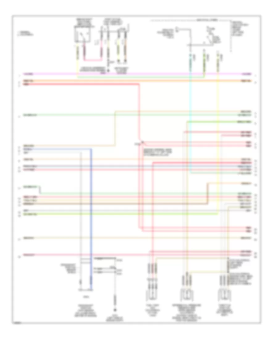
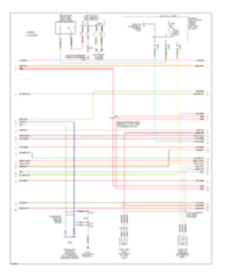
5.4L
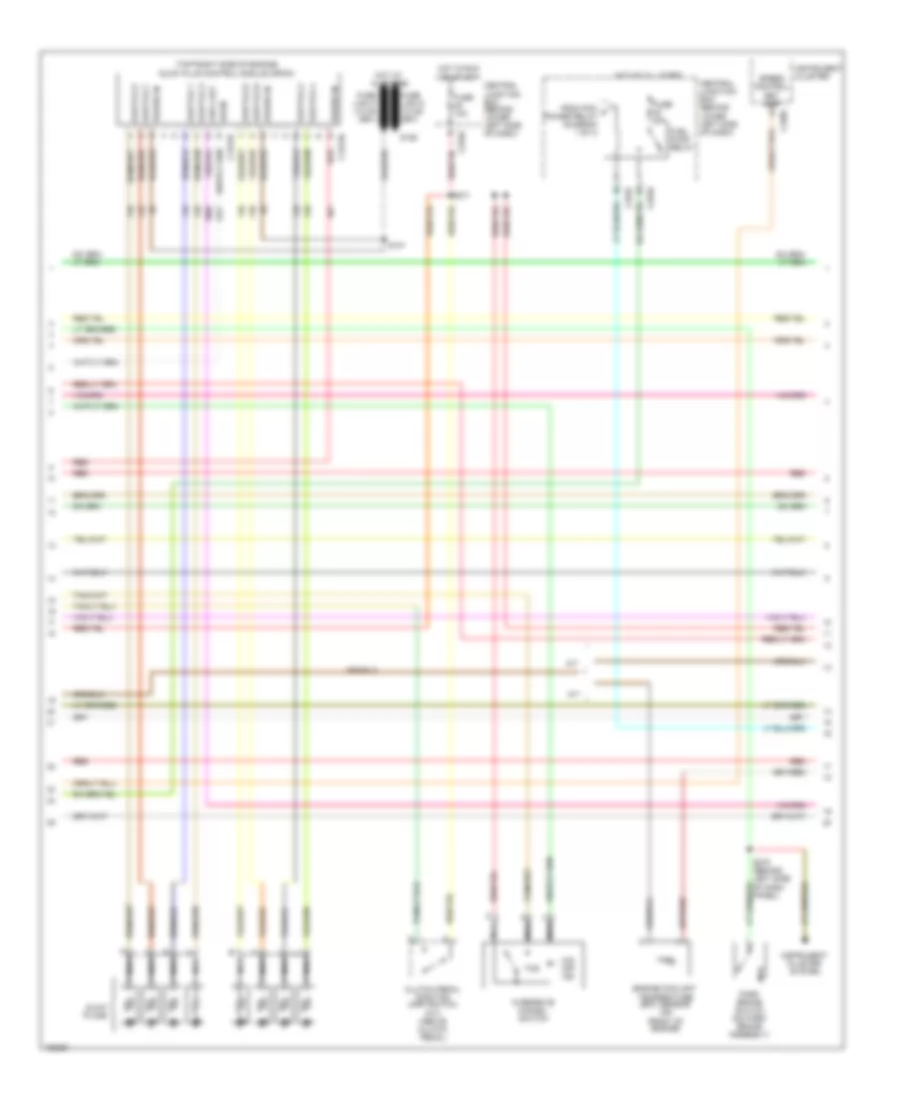
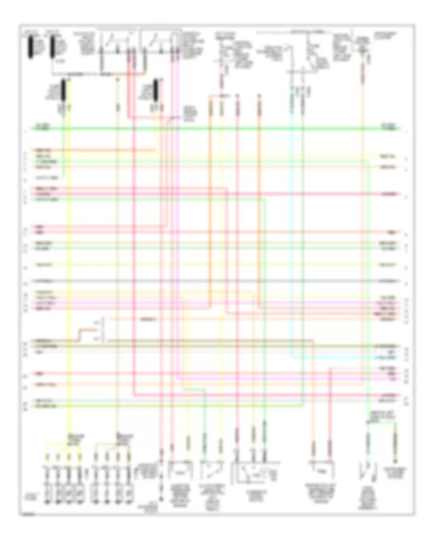
5.4L, Engine Performance Wiring Diagram (1 of 4) for Ford Cab & Chassis F350 Super Duty 2002

List of elements for 5.4L, Engine Performance Wiring Diagram (1 of 4) for Ford Cab & Chassis F350 Super Duty 2002:
- (engine sensor harn, near breakout at right side of engine, above cylinder 3)
- (left front g300 footwell)
- (left rear of engine compt)
- (main harn, near breakout at center of dash, on dlc)
- (not used)
- A/c press sw
- A/c system
- Acc
- Anti-theft system
- C270a
- Ccs
- Central junction box (behind lower left side of dash)
- Ckp(+)
- Ckp(-)
- Coil on plug
- Cust access
- Customer access
- Data link (+)
- Data link (-)
- Data link connector (dlc) (behind center of dash)
- Data output
- Diag grd
- Digital transmission range (dtr) sensor (on left side of transmission)
- Egr sol
- Fuel pump mon
- Fuse 10a
- Fuse 20a
- Fuse 30a
- G100
- G101 (left side of engine compt)
- Hego 12
- Hot at all times
- Hot in run or start
- Iat
- Ign coil 1
- Ign coil 3
- Ign coil 5
- Ign coil 6
- Ignition transformer capacitor (on left side of engine)
- Ignition transformer capacitor (on right side of engine)
- Knock sensor
- Lock
- Maf
- Nca
- Not used
- O/d off ind
- Off
- Overdrive cancel switch
- Overhead console
- Pcm power diode
- Pcm power relay
- Powertrain control module (pcm) (on left side of firewall)
- Pwr gnd
- R n
- Red
- Reprog pwr
- Run
- S106
- S130 (engine harn, near breakout at throttle body)
- S135
- S201
- S258
- S271
- S284
- S286
- Shift sol 1
- Shift sol 2
- Start
- Tcs
- Tft
- To dtr sensor (diagram 4 of 4)
- To fuel pump relay (diagram 2 of 4)
- Tr1
- Tr2
- Tr4
- Trans ctrl ind
- Transmission control switch
- Vss (-)
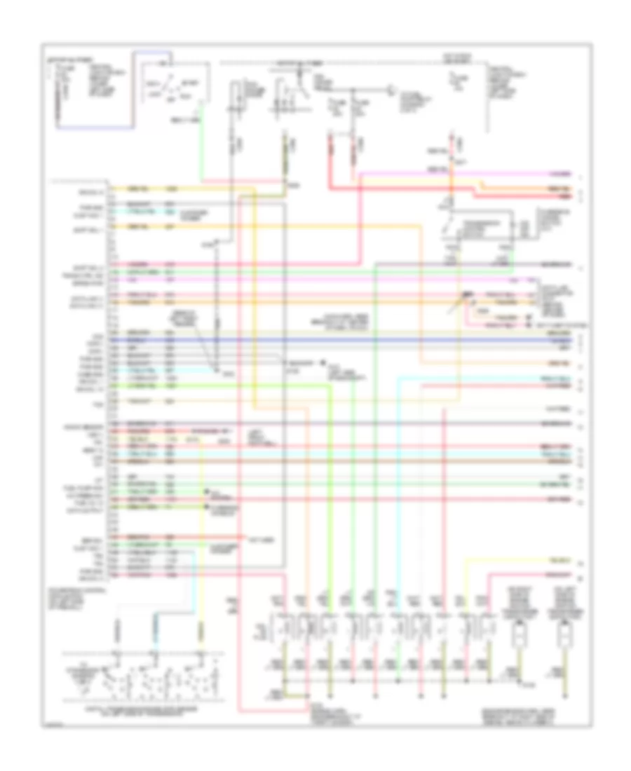
5.4L, Engine Performance Wiring Diagram (2 of 4) for Ford Cab & Chassis F350 Super Duty 2002
List of elements for 5.4L, Engine Performance Wiring Diagram (2 of 4) for Ford Cab & Chassis F350 Super Duty 2002:
- (behind right kick panel) inertia fuel shut-off switch
- (engine harness, near breakout at left side of steering column)
- (part of fuel tank assembly) fuel tank unit
- C270a
- C270f
- C270h
- Central junction box (behind lower left side of dash)
- Crankshaft position (ckp) sensor (on lower front center of engine)
- Crankshaft position sensor shield
- Differential pressure feedback egr (dpfe) sensor (california) (on right side of engine, near throttle position sensor)
- Federal california
- From pcm power relay (diagram 1 of 4)
- Fuel pump relay
- Fuel tank unit (california) (at fuel tank)
- Fuse 20a
- G101 (left side of engine compt)
- Hot at all times
- Instrument cluster system
- Nca
- Red
- Red/pnk
- S123
- S133 (california) (engine harn, near breakout at left side of engine, above cylinder 6)
- S145
- S161
- S167
- S170 (california) (left rear of engine compt)
- S401
- Throttle position (tp) sensor (on throttle body)
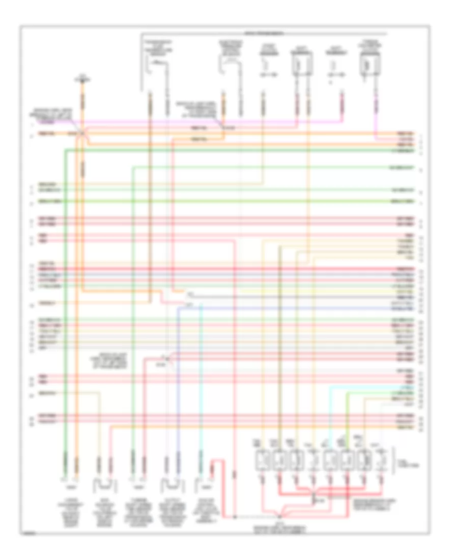
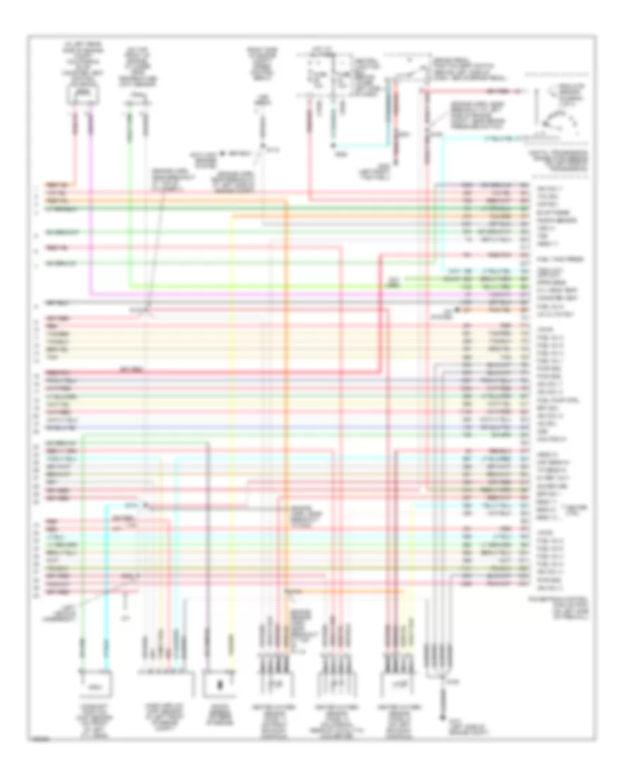
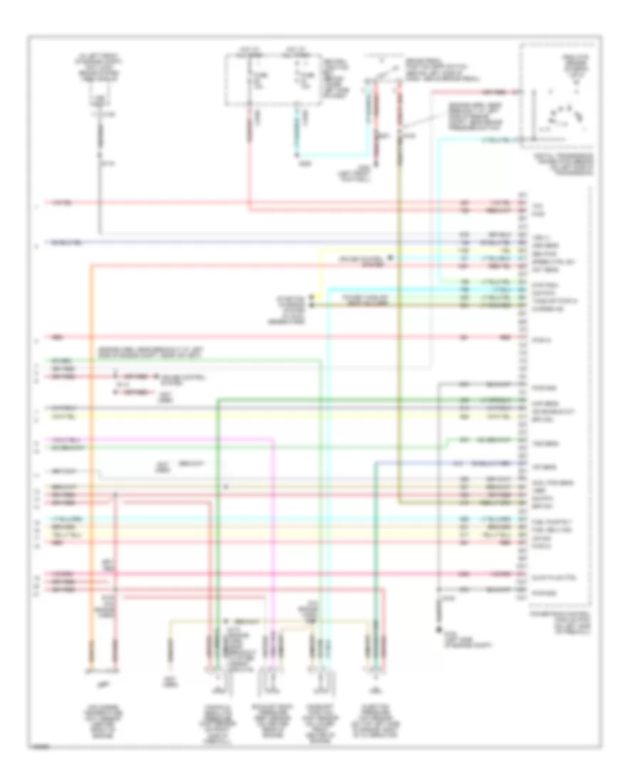
5.4L, Engine Performance Wiring Diagram (3 of 4) for Ford Cab & Chassis F350 Super Duty 2002
List of elements for 5.4L, Engine Performance Wiring Diagram (3 of 4) for Ford Cab & Chassis F350 Super Duty 2002:
- (back-up lamp harn, near break- out at left side of transmission)
- (back-up lamp harn, near breakout at right side of transmission)
- (engine harn, near breakout at left of steering column)
- (engine sensor harn, near breakout at top of cylinder 3)
- (on right rear of engine compt)
- 4r100 transmission
- A/c system
- A/t
- Coast clutch solenoid
- Electronic pressure control solenoid
- Evr solenoid valve (california) (on left side of engine)
- Fuel injectors
- Idle air control (iac) valve (on throttle body assembly)
- M/t
- Output shaft speed (oss) sensor (on top of transmission extension housing)
- Red
- Red/pnk
- S122
- S131 (engine harn, near break- out at top of cylinder 7)
- S136
- S138
- S139
- Shift solenoid 1
- Shift solenoid 2
- Tan
- Tan/ red
- Tan/red
- Torque converter clutch solenoid
- Transmission fluid temperature sensor
- Turbine shaft speed (tss) sensor (on top of transmission, at converter housing)
- Vapor management valve
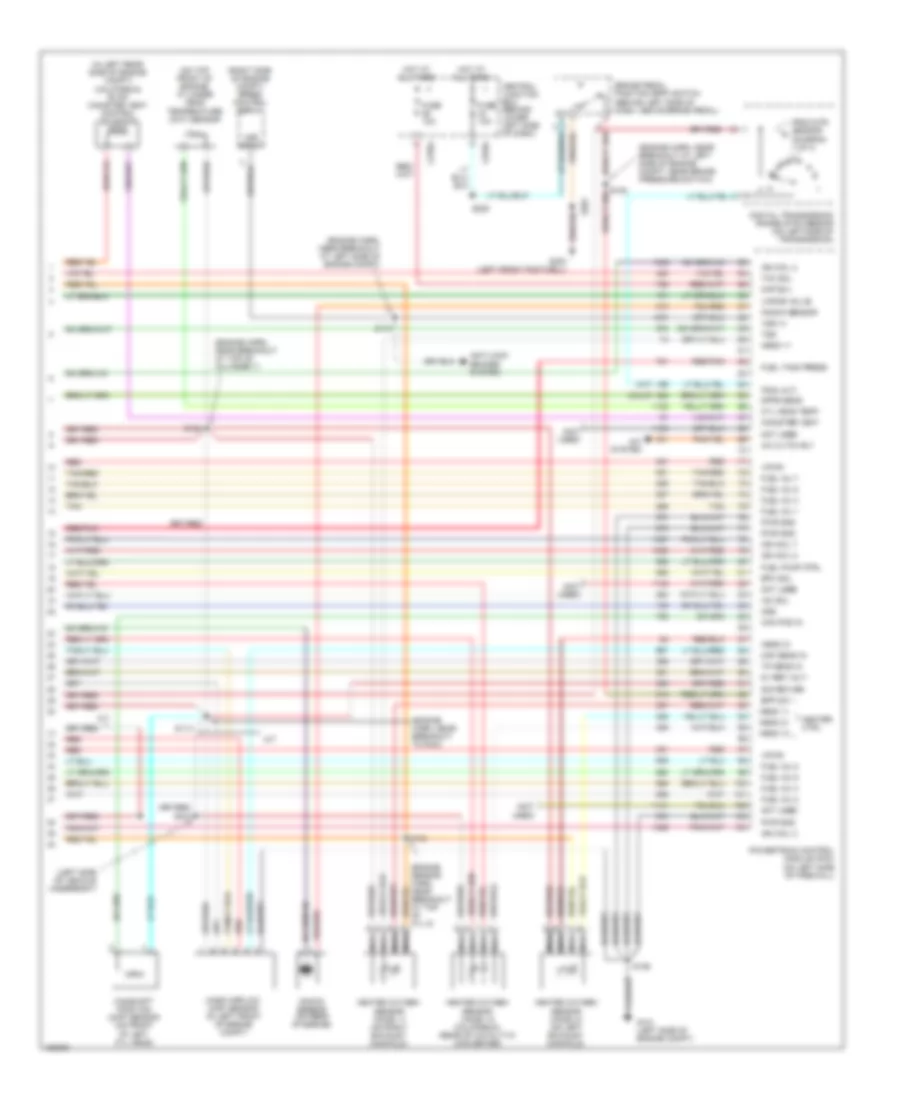
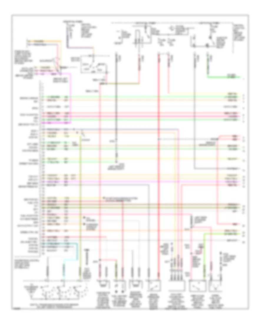
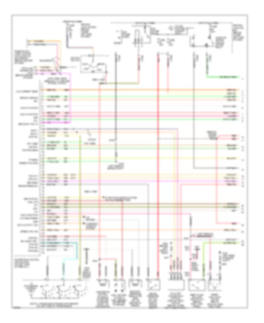
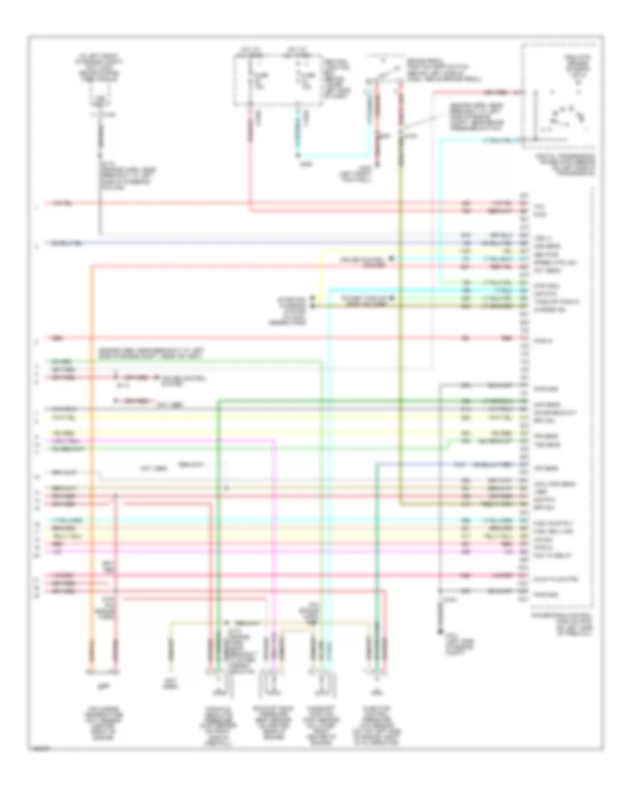
5.4L, Engine Performance Wiring Diagram (4 of 4) for Ford Cab & Chassis F350 Super Duty 2002
List of elements for 5.4L, Engine Performance Wiring Diagram (4 of 4) for Ford Cab & Chassis F350 Super Duty 2002:
- (a/t)
- (calif)
- (engine harn, near breakout at left side of engine compt)
- (engine harn, near breakout at left side of engine compt, near brake pressure switch)
- (engine harn, near breakout at top of cylinder 7)
- (engine harn, near breakout to pcm)
- (in left rear side of engine compt) (california) evap canister vent control solenoid
- (left side of vehicle underbody)
- (not used)
- (on top front of engine) cylinder head temperature (cht) sensor
- (right side of engine compt) speed control servo
- 5v ref volt
- A/c cltch rly
- A/c system
- A/t
- Anti-lock brakes system
- Bpp sw
- Brake pedal position (bpp) switch (behind left side of dash, above brake pedal)
- C270a
- C270g
- Cam pos in
- Camshaft position (cmp) sensor (on front of left cyl head)
- Canister vent
- Central junction box (behind lower left side of dash)
- Cyl 8)
- Cyl head temp
- Digital transmission range (dtr) sensor (on left side of transmission)
- Dpfe sens
- Epc sol
- From dtr sensor (diagram 1 of 4)
- Fuel inj 1
- Fuel inj 2
- Fuel inj 3
- Fuel inj 4
- Fuel inj 5
- Fuel inj 6
- Fuel inj 7
- Fuel inj 8
- Fuel pump ctrl
- Fuel tank press
- Fuse 10a
- G101 (left side of engine compt)
- G300 (left front footwell)
- Heated oxygen sensor (ho2s) 11 (on right exhaust manifold)
- Heated oxygen sensor (ho2s) 12 (california) (rear of catalytic converter)
- Heated oxygen sensor (ho2s) 21 (on left exhaust manifold)
- Heater ctrl
- Hego 11
- Hego 12
- Hego 21
- Hot at all times
- Iac sol
- Ign coil 2
- Ign coil 4
- Ign coil 7
- Ign coil 8
- Kap b(+)
- Knock sensor
- Knock sensor (on rear of engine)
- M/t
- Maf sens in
- Mass airflow (maf) sensor (in left front of engine compt)
- Nca
- Not used
- Oss
- Powertrain control module (pcm) (on left side of firewall)
- Pwr gnd
- Red
- Red/pnk
- S106
- S114
- S115
- S132
- S134
- S228
- S343
- Sig return
- Tan
- Tan/red
- Tcc sol
- Tp sens in
- Tr3a (a/t)
- Tss
- Vapor valve
- Vpwr
- Vss (+)
- Vss input
6.8L
6.8L, Engine Performance Wiring Diagram (1 of 4) for Ford Cab & Chassis F350 Super Duty 2002
List of elements for 6.8L, Engine Performance Wiring Diagram (1 of 4) for Ford Cab & Chassis F350 Super Duty 2002:
- (engine sensor harn, near breakout at right side of engine, above cylinder 3)
- (left front footwell)
- (main harn, near breakout at center of dash, on dlc)
- (on left side of engine) ignition transformer capacitor 2
- (on right side of engine) ignition transformer capacitor 1
- (rear of left front fender)
- A/c press sw
- A/c system
- Acc
- Anti-theft system
- C270a
- Case gnd
- Ccs
- Central junction box (behind lower left side of dash)
- Ckp(+)
- Ckp(-)
- Coil on plug
- Cust acc 1
- Customer access
- Data link (+)
- Data link (-)
- Data link connector (dlc) (behind center of dash)
- Data output
- Digital transmission range (dtr) sensor (on left side of transmission)
- Egr sol
- Eprom pwr
- Fuel inj 10
- Fuel pump mon
- Fuse 10a
- Fuse 20a
- Fuse 30a
- G100
- G101 (left side of eng compt)
- G300
- Hego 12
- Hot at all times
- Hot in run or start
- Iat
- Ign coil 1
- Ign coil 10
- Ign coil 5
- Ign coil 6
- Knock sensor
- Lock
- Maf
- Nca
- Not used
- O/d off ind
- Off
- Overdrive cancel switch (a/t)
- Overhead console
- Pcm power diode
- Pcm power relay
- Powertrain control module (pcm) (on left side of firewall)
- Pwr gnd
- R n
- Red
- Run
- S106
- S130 (engine harn, near breakout at throttle body)
- S135
- S162
- S172
- S258
- S271
- S284
- S286
- Shift sol 1
- Shift sol 2
- Start
- Tcs
- Tft
- To dtr sensor (diagram 4 of 4)
- To fuel pump relay (diagram 2 of 4)
- Tr1
- Tr2
- Tr4
- Trans ctrl ind
- Transmission control switch
- Vss (-)
6.8L, Engine Performance Wiring Diagram (2 of 4) for Ford Cab & Chassis F350 Super Duty 2002
List of elements for 6.8L, Engine Performance Wiring Diagram (2 of 4) for Ford Cab & Chassis F350 Super Duty 2002:
- (behind right kick panel) inertia fuel shut-off switch
- (engine harness, near breakout at left side of steering column)
- (part of fuel tank assembly) fuel tank unit
- (vehicle underbody chassis side member) g104
- C270a
- C270f
- C270h
- California
- Central junction box (behind lower left side of dash)
- Crankshaft position (ckp) sensor (on lower front center of engine)
- Crankshaft position sensor shield
- Federal
- From pcm power relay (diagram 1 of 4)
- Fuel pump relay
- Fuel tank unit (california) (at fuel tank)
- Fuse 20a
- G102 (left side of firewall)
- Hot at all times
- Instrument cluster system
- Nca
- Red
- Red/pnk
- S123
- S145
- S161
- S167
- S170 (california) (left rear of engine)
- S401
- Throttle position (tp) sensor (on throttle body)
6.8L, Engine Performance Wiring Diagram (3 of 4) for Ford Cab & Chassis F350 Super Duty 2002
List of elements for 6.8L, Engine Performance Wiring Diagram (3 of 4) for Ford Cab & Chassis F350 Super Duty 2002:
- (back-up lamp harn, near breakout at left side of transmission)
- (back-up lamp harn, near breakout at right side of transmission)
- (engine harn, near breakout at left of steering column)
- (on right rear of engine compt)
- 4r100 transmission
- A/c system
- A/t
- Coast clutch solenoid
- Electronic pressure controller
- Fuel injectors
- Idle air control (iac) valve (on throttle body assembly)
- M/t
- Output shaft speed (oss) sensor (on top of transmission extension housing)
- Red
- Red/pnk
- S122
- S131 (engine harn, near break- out at top of cylinder 7)
- S136 (engine sensor harn, near break- out at top of cylinder 3)
- S138
- S139
- Shift solenoid 1
- Shift solenoid 2
- Tan
- Tan/ red
- Tan/red
- Torque converter clutch solenoid
- Transmission fluid temperature sensor
- Turbine shaft speed (tss) sensor (on top of transmission, at converter housing)
- Vapor management valve
6.8L, Engine Performance Wiring Diagram (4 of 4) for Ford Cab & Chassis F350 Super Duty 2002
List of elements for 6.8L, Engine Performance Wiring Diagram (4 of 4) for Ford Cab & Chassis F350 Super Duty 2002:
- (a/t)
- (calif)
- (engine harn, near breakout at left side of engine compt)
- (engine harn, near breakout at left side of engine compt, near brake pressure switch)
- (engine harn, near breakout at top of cylinder 7)
- (engine harn, near breakout to pcm)
- (in left rear side of engine compt) (california) evap canister vent control solenoid
- (left vehicle underbody)
- (on top front of engine) cylinder head temperature (cht) sensor
- (right side of engine compt) speed control servo
- 5v ref volt
- A/c cltch rly
- A/c system
- A/t
- Anti-lock brakes system
- Bpp sw
- Brake pedal position (bpp) switch (behind left side of dash, above brake pedal)
- C270a
- C270g
- Cam pos in
- Camshaft position (cmp) sensor (on front of left cyl head)
- Canister vent
- Central junction box (behind lower left side of dash)
- Cyl 8)
- Cyl head temp
- Digital transmission range (dtr) sensor (on left side of transmission)
- Dpfe sens
- Epc sol
- Evap purge
- From dtr sensor (diagram 1 of 4)
- Fuel inj 1
- Fuel inj 2
- Fuel inj 3
- Fuel inj 4
- Fuel inj 5
- Fuel inj 6
- Fuel inj 8
- Fuel inj 9
- Fuel pump ctrl
- Fuel tank press
- Fuse 10a
- G101 (left side of engine compt)
- G300 (left front footwell)
- Heated oxygen sensor (ho2s) 11 (on right exhaust manifold)
- Heated oxygen sensor (ho2s) 12 (california) (rear of catalytic converter)
- Heated oxygen sensor (ho2s) 21 (on left exhaust manifold)
- Heater ctrl
- Hego 11
- Hego 12
- Hego 21
- Hot at all times
- Iac sol
- Ign coil 3
- Ign coil 4
- Ign coil 7
- Ign coil 8
- Ign coil 9
- Kap b(+)
- Knock sensor
- Knock sensor (on rear of engine)
- M/t
- Maf sens in
- Mass airflow (maf) sensor (in left front of engine compt)
- Nca
- Not used
- Oss
- Powertrain control module (pcm) (on left side of firewall)
- Pwr gnd
- Red
- Red/pnk
- S106
- S114
- S115
- S132
- S134
- S228
- S343
- Sig return
- Tan
- Tan/red
- Tcc sol
- Tp sens in
- Tr3a (a/t) cpp (m/t)
- Tss
- Vpwr
- Vss (+)
- Vss input
7.3L DI TURBO DIESEL
7.3L DI Turbo Diesel, Engine Performance Wiring Diagram, California (1 of 4) for Ford Cab & Chassis F350 Super Duty 2002
List of elements for 7.3L DI Turbo Diesel, Engine Performance Wiring Diagram, California (1 of 4) for Ford Cab & Chassis F350 Super Duty 2002:
- (a/t)
- (behind center of dash)
- (behind left side of dash)
- (left rear of engine compt)
- (m/t)
- (not used)
- (rear of engine compt)
- A/c head press
- A/c system
- Acc
- Auxiliary powertrain control module (apcm) (pickup) (behind lower right side of dash)
- Brake press sw
- Brake pressure switch (on left side of engine compt)
- Brake warning
- Bus (+)
- Bus (-)
- Cam pos sens
- Ccs sol
- Central junction box (behind lower left side of dash)
- Cpp (m/t)
- Dash)
- Data link connector (dlc)
- Data output link
- Diesel fuel pump motor (below vehicle, near fuel tank)
- Digital transmission range (dtr) sensor (on left side of transmission)
- Dsl elect drv
- Dtr-tr1
- Dtr-tr2
- Dtr-tr4
- Ebp sens
- Eot
- Epr
- Excursion
- Exhaust pressure regulator (epr) (on top center of engine)
- Fuel heater/ water in fuel sensor (on center of engine)
- Fuel htr
- Fuel pump pwr
- Fuse 20a
- Fuse 30a
- G100 (left rear of engine compt)
- G101 (left side of engine compt)
- Gen pwr sw
- Gen scan tool in
- Gpcm
- Hot at all times
- Iat
- Idle validation
- Ignition switch
- Inertia fuel shutoff (ifs) switch (behind right kick panel)
- Injector driver module power relay
- Lock
- Nca
- Not used
- Off
- Overhead console system
- Passive anti- theft system (pats) module (excursion) (behind center of dash)
- Pcm power diode
- Pcm power relay
- Pickup
- Powertrain control module (pcm) (on left side of firewall)
- Pwr gnd
- R n
- Red
- Run
- S106
- S123
- S141
- S154
- S162
- S217
- S250
- S258
- S260 (behind right side of dash)
- S284
- S286
- Speed ctrl ind
- Speed/tach gnd
- Ss1
- Ss2
- Start
- Starting/charging system (w/ dual generators)
- Tcil
- Tcs (a/t)
- Tft
- To dtr sensor (diagram 4 of 4)
- To fuel pump relay (diagram 2 of 4)
- Tp sens
- Wastegate control solenoid (in center of engine compt, on wastegate)
- Wcs sol
7.3L DI Turbo Diesel, Engine Performance Wiring Diagram, California (2 of 4) for Ford Cab & Chassis F350 Super Duty 2002
List of elements for 7.3L DI Turbo Diesel, Engine Performance Wiring Diagram, California (2 of 4) for Ford Cab & Chassis F350 Super Duty 2002:
- (top right side of engine) glow plug control module (gpcm)
- A/t
- C1273a
- C1273b
- C270a
- C270f
- Central junction box (behind lower left side of dash)
- Clutch pedal position (cpp) switch (m/t) (above clutch pedal)
- Cntl out
- Engine coolant temperature (ect) sensor (on front of engine)
- From pcm a power relay (diagram 1 of 4)
- Fuel pump relay
- Fuse 10a
- Fuse 20a
- Glow plugs
- Glw plg 1
- Glw plg 2
- Glw plg 3
- Glw plg 4
- Glw plg 5
- Glw plg 6
- Glw plg 7
- Glw plg 8
- Gpcm
- Hot at all times
- Hot in run or start
- Instrument cluster
- Instrument cluster system
- M/t
- Nca
- O/d off ind
- Overdrive cancel switch
- Park brake switch (on park brake assembly)
- Power in
- Red
- S126
- S147
- S271
- S278 (behind left side of dash panel)
- Speed control set lamp c220c
- Tcs
7.3L DI Turbo Diesel, Engine Performance Wiring Diagram, California (3 of 4) for Ford Cab & Chassis F350 Super Duty 2002
List of elements for 7.3L DI Turbo Diesel, Engine Performance Wiring Diagram, California (3 of 4) for Ford Cab & Chassis F350 Super Duty 2002:
- (back-up lamp harn, near breakout at left side of transmission)
- (back-up lamp harn, near breakout at right side of transmission)
- (in left side of engine compt) injector driver module (idm)
- Accelerator pedal position sensor (above brake pedal)
- Automatic transmission module
- Cid sig in
- Coast clutch solenoid
- Electronic pressure control solenoid
- Engine oil temperature (eot) sensor (on top front of engine)
- Feedback
- Fuel inj 1
- Fuel inj 2
- Fuel inj 3
- Fuel inj 4
- Fuel inj 5
- Fuel inj 6
- Fuel inj 7
- Fuel inj 8
- Fuel injectors
- Fuel sig
- G101 (left side of engine compt)
- Inj feed
- Intake air temperature sensor (left side of engine compt, behind air cleaner)
- Nca
- Output shaft speed (oss) sensor (on top of transmission extension housing)
- Pwr gnd
- Pwr in
- Red
- S138
- S139
- Shield
- Shift solenoid
- Sig rtn
- Tan
- Tan/red
- Torque converter clutch solenoid
- Transmission fluid temperature sensor
- Turbine shaft speed (tss) sensor (on top of transmission, at converter housing)
7.3L DI Turbo Diesel, Engine Performance Wiring Diagram, California (4 of 4) for Ford Cab & Chassis F350 Super Duty 2002
List of elements for 7.3L DI Turbo Diesel, Engine Performance Wiring Diagram, California (4 of 4) for Ford Cab & Chassis F350 Super Duty 2002:
- (engine harn, near breakout at left side of engine compt, near air vent)
- (engine harn, near breakout at left side of engine compt, near brake pressure switch)
- (in left front of engine compt) anti-lock brake system (abs) module
- (not used)
- (pia engine harn) s151
- Accl pos sens
- Act sens
- Air charge temperature (act) sensor (center front of engine)
- Bpp sw
- Brake pedal position (bpp) switch (behind left side of dash, above brake pedal)
- C135
- C270a
- C270g
- Camshaft position (cmp) sensor (on lower front center of engine)
- Central junction box (behind lower left side of dash)
- Charge ind
- Cid sig
- Cmp rtn
- Cruise control system
- Digital transmission range (dtr) sensor (on left side of transmission)
- Dtr-tr3a
- Epc sol
- Exhaust back pressure (ebp) sensor (on center rear of engine)
- From dtr sensor (diagram 1 of 4)
- Fuel deliv sig
- Fuel pump rly
- Fuse 10a
- G102 (left side of engine compt)
- G300 (left front footwell)
- Gen pwr
- Glow plug ctrl
- Hot at all times
- Icp sens
- Idm enable out
- Injection pressure (icp) sensor (on top left side of engine, right of alternator)
- Manifold absolute pressure (map) sensor (on right side of firewall)
- Map sens
- Oss sens
- Power take off (body builder)
- Powertrain control module (pcm) (on left side of firewall)
- Pwr
- Pwr gnd
- Pwr in
- Red
- S106
- S114
- S115
- S153 (pia engine harn)
- S228
- Sig rtn
- Speed ctrl sw
- Starting/ charging system (w/ dual generators)
- Take off pwr in
- Tcc
- Tss sens
- Vref
- Vss (+)
- Vss out
7.3L DI Turbo Diesel, Engine Performance Wiring Diagram, Federal (1 of 4) for Ford Cab & Chassis F350 Super Duty 2002
List of elements for 7.3L DI Turbo Diesel, Engine Performance Wiring Diagram, Federal (1 of 4) for Ford Cab & Chassis F350 Super Duty 2002:
- (a/t)
- (behind center of dash)
- (left rear of engine compt)
- (m/t)
- (main harn, near breakout at center of dash, on dlc)
- (rear of engine compt) s123
- A/c head press
- A/c system
- Acc
- Auxiliary powertrain control module (apcm) (pickup) (behind lower right side of dash)
- Brake press sw
- Brake pressure switch (on left side of engine compt)
- Brake warning
- Bus (+)
- Bus (-)
- Cam pos sens
- Ccs sol
- Central junction box (behind lower left side of dash)
- Cpp (m/t)
- Dash)
- Data link connector (dlc)
- Data output link
- Diesel fuel pump motor (below vehicle, near fuel tank)
- Digital transmission range (dtr) sensor (on left side of transmission)
- Dsl elect drv
- Dtr-tr1
- Dtr-tr2
- Dtr-tr4
- Ebp sens
- Eot
- Epr
- Excursion
- Exhaust pressure regulator (epr) (on top center of engine)
- Fuel heater/ water in fuel sensor (on center of engine)
- Fuel htr
- Fuel pump pwr
- Fuse 20a
- Fuse 30a
- G100 (left rear of engine compt)
- G102 (left side of engine compt)
- Gen pwr sw
- Gen scan tool in
- Glow plug mon
- Hot at all times
- Iat
- Idle validation
- Ignition switch
- Inertia fuel shutoff (ifs) switch (behind right kick panel)
- Injector driver module power relay
- Lock
- Low current sens
- Nca
- Not used
- Off
- Overhead console system
- Passive anti- theft system (pats) module (excursion) (behind center of dash)
- Pcm power diode
- Pcm power relay
- Pickup
- Powertrain control module (pcm) (on left side of firewall)
- Pwr gnd
- R n
- Red
- Run
- S106
- S141
- S154
- S162
- S217
- S250
- S258
- S260 (right dash panel)
- S284
- S286
- Speed ctrl ind
- Speed/tach gnd
- Ss1
- Ss2
- Start
- Starting/charging system (w/ dual generators)
- Tcil
- Tcs (a/t)
- Tft
- To dtr sensor (diagram 4 of 4)
- To fuel pump relay (diagram 2 of 4)
- Tp sens
- Wastegate control solenoid (in center of engine compt, on wastegate)
- Wcs sol
7.3L DI Turbo Diesel, Engine Performance Wiring Diagram, Federal (2 of 4) for Ford Cab & Chassis F350 Super Duty 2002
List of elements for 7.3L DI Turbo Diesel, Engine Performance Wiring Diagram, Federal (2 of 4) for Ford Cab & Chassis F350 Super Duty 2002:
- (behind left side of dash) s278
- (right engine compt) s1002
- A/t
- C1279
- C1280
- C270a
- C270f
- Central junction box (behind lower left side of dash)
- Clutch pedal position (cpp) switch (m/t) (above clutch pedal)
- Engine coolant temperature (ect) sensor (on front of engine)
- From pcm a power relay (diagram 1 of 4)
- Fuel pump relay
- Fuse 10a
- Fuse 20a
- G111 (on engine block)
- Glow plug relay (on left side of engine compt)
- Glow plugs
- Hot at all times
- Hot in run or start
- Injector pressure sensor (on top center of engine)
- Instrument cluster
- Instrument cluster system
- M/t
- Manifold intake air heater 58 amp
- Manifold intake air heater relay (in center of engine compt)
- Nca
- O/d off ind
- Overdrive cancel switch
- Park brake switch (on park brake assembly)
- Red
- S126
- S150
- S271
- Speed control set lamp c270c
- Tcs
7.3L DI Turbo Diesel, Engine Performance Wiring Diagram, Federal (3 of 4) for Ford Cab & Chassis F350 Super Duty 2002
List of elements for 7.3L DI Turbo Diesel, Engine Performance Wiring Diagram, Federal (3 of 4) for Ford Cab & Chassis F350 Super Duty 2002:
- (back-up lamp harn, near breakout at left side of transmission)
- (back-up lamp harn, near breakout at right side of transmission)
- (in left side of engine compt) injector driver module (idm)
- Automatic transmission module
- Cid sig in
- Coast clutch solenoid
- Electronic pressure control solenoid
- Engine oil temperature (eot) sensor (on top front of engine)
- Feedback
- Fuel inj 1
- Fuel inj 2
- Fuel inj 3
- Fuel inj 4
- Fuel inj 5
- Fuel inj 6
- Fuel inj 7
- Fuel inj 8
- Fuel injectors
- Fuel sig
- G101 (left side of engine compt)
- Inj feed
- Intake air temperature sensor (left side of engine compt, behind air cleaner)
- Nca
- Output shaft speed (oss) sensor (on top of transmission extension housing)
- Pwr gnd
- Pwr in
- Red
- S138
- S139
- Shield
- Shift solenoid
- Sig rtn
- Tan
- Tan/red
- Throttle pedal position sensor (late production) (above brake pedal)
- Torque converter clutch solenoid
- Transmission fluid temperature sensor
- Turbine shaft speed (tss) sensor (on top of transmission, at converter housing)
7.3L DI Turbo Diesel, Engine Performance Wiring Diagram, Federal (4 of 4) for Ford Cab & Chassis F350 Super Duty 2002
List of elements for 7.3L DI Turbo Diesel, Engine Performance Wiring Diagram, Federal (4 of 4) for Ford Cab & Chassis F350 Super Duty 2002:
- (engine harn, near breakout at left side of engine compt, near air vent)
- (engine harn, near breakout at left side of engine compt, near brake pressure switch)
- (in left front of engine compt) anti-lock brake system (abs) module
- (not used)
- (pia engine harn) s151
- Accl pos sens
- Act sens
- Air charge temperature (act) sensor (center front of engine)
- Bpp sw
- Brake pedal position (bpp) switch (behind left side of dash, above brake pedal)
- C135
- C270a
- C270g
- Camshaft position (cmp) sensor (on lower front center of engine)
- Central junction box (behind lower left side of dash)
- Charge ind
- Cid sig
- Cmp rtn
- Cruise control system
- Digital transmission range (dtr) sensor (on left side of transmission)
- Dtr-tr3a
- Epc sol
- Exhaust back pressure (ebp) sensor (on center rear of engine)
- From dtr sensor (diagram 1 of 4)
- Fuel deliv sig
- Fuel pump rly
- Fuse 10a
- G101 (left side of engine compt)
- G300 (left front footwell)
- Gen pwr
- Glow plug ctrl
- Hot at all times
- Icp sens
- Idm enable out
- Injection control pressure (icp) sensor (on top left side of engine, right of alternator)
- Ipr sens
- Manifold absolute pressure (map) sensor (on right side of firewall)
- Map sens
- Not used
- Oss sens
- Pcm to relay
- Power take off (body builder)
- Powertrain control module (pcm) (on left side of firewall)
- Pwr
- Pwr gnd
- Pwr in
- Red
- S106
- S114
- S115 (engine harn, near breakout at left side of steering column)
- S153 (pia engine harn)
- S228
- Sig rtn
- Speed ctrl sw
- Starting/ charging system (w/ dual generators)
- Take off pwr in
- Tcc
- Tss sens
- Vref
- Vss (+)
- Vss out