HORN
Horn Wiring Diagram for Ford Cutaway E350 1996
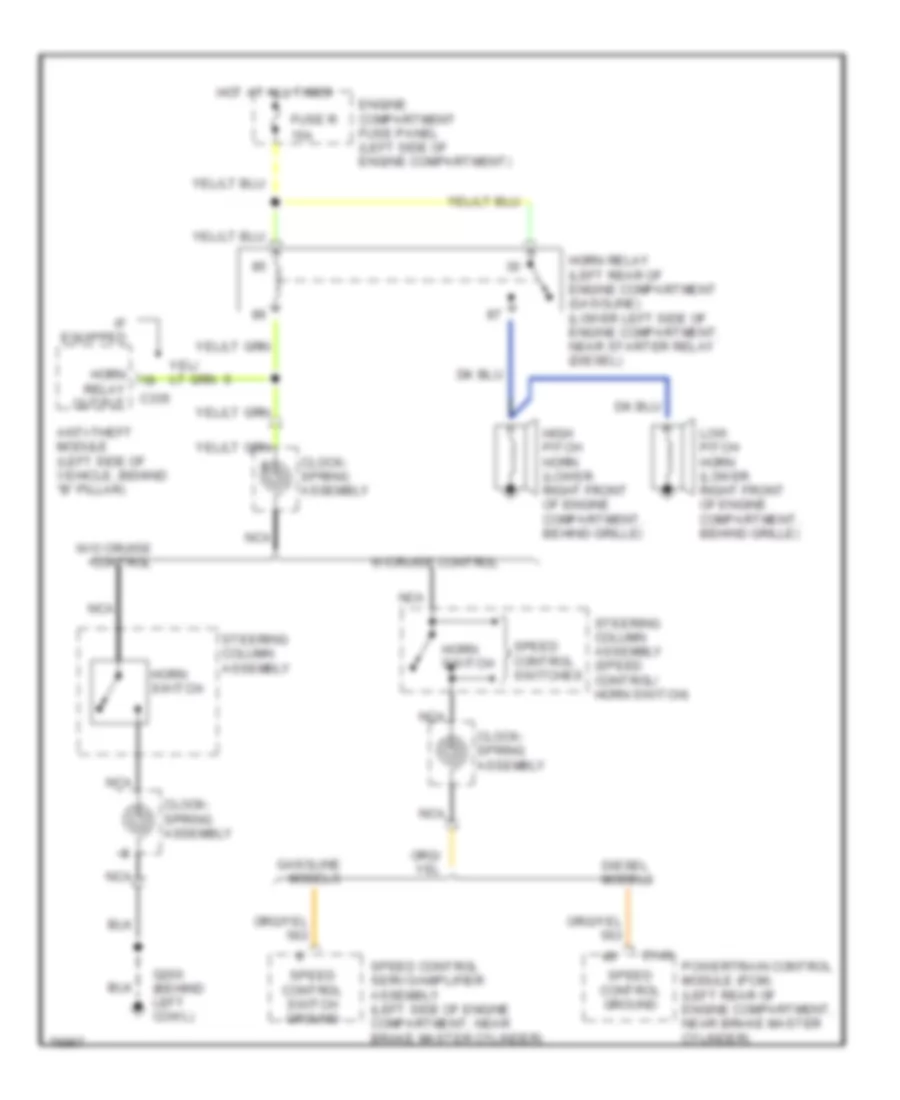
List of elements for Horn Wiring Diagram for Ford Cutaway E350 1996:
- 15a
- Anti-theft module (left side of vehicle, behind "b" pillar)
- C143
- C335
- Clock- spring assembly
- Diesel models
- Engine compartment fuse panel (left side of engine compartment)
- Fuse r
- G200 (behind left cowl)
- Gasoline models
- High pitch horn (lower right front of engine compartment, behind grille)
- Horn
- Horn relay (left rear of engine compartment (gasoline) (lower left side of engine compartment, near starter relay (diesel)
- Horn switch
- Hot at all times
- If equipped
- Low pitch horn (lower right front of engine compartment, behind grille)
- Nca
- Powertrain control module (pcm) (left rear of engine compartment, near brake master cylinder)
- Relay output
- Speed control ground
- Speed control servo/amplifier assembly (left side of engine compartment, near brake master cylinder)
- Speed control switch ground
- Speed control switches
- Steering column assembly
- Steering column assembly (speed control/ horn switch)
- W/cruise control
- W/o cruise control
 Čeština
 Dansk
Dansk Deutsch
 Ελληνικά
 English
 English
 Español
 Suomi
Suomi Français
 Français
 עברית
עברית Hrvatski
 Magyar
 Italiano
 日本語
日本語 한국어
한국어 Nederlands
 Polski
 Português
 Română
 Русский
 Slovenčina
 Slovenščina
 Svenska
 Türkçe
 中文 (中国)
 Português