Čeština
 Dansk
Dansk Deutsch
 Ελληνικά
 English
 English
 Español
 Suomi
Suomi Français
 Français
 עברית
עברית Hrvatski
 Magyar
 Italiano
 日本語
日本語 한국어
한국어 Nederlands
 Polski
 Português
 Română
 Русский
 Slovenčina
 Slovenščina
 Svenska
 Türkçe
 中文 (中国)

ELECTRONIC SUSPENSION
Computer Command Ride for Pontiac Bonneville SE 1995


List of elements for Computer Command Ride for Pontiac Bonneville SE 1995:
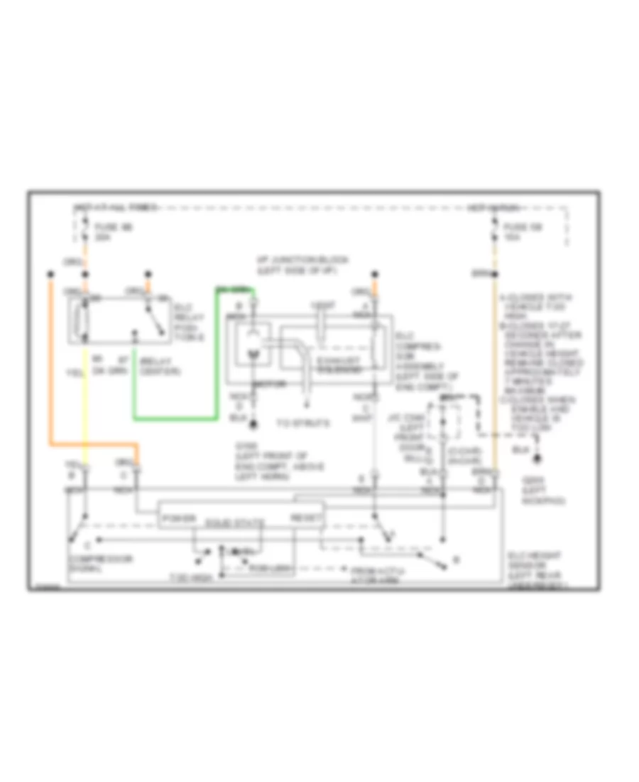
Electronic Level Control (with Assembly Inflator) for Pontiac Bonneville SE 1995
List of elements for Electronic Level Control (with Assembly Inflator) for Pontiac Bonneville SE 1995:
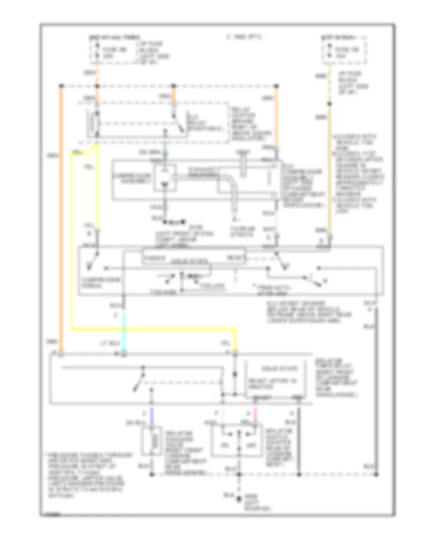
Electronic Level Control (without Assembly Inflator) for Pontiac Bonneville SE 1995
List of elements for Electronic Level Control (without Assembly Inflator) for Pontiac Bonneville SE 1995: