Čeština
 Dansk
Dansk Deutsch
 Ελληνικά
 English
 English
 Español
 Suomi
Suomi Français
 Français
 עברית
עברית Hrvatski
 Magyar
 Italiano
 日本語
日本語 한국어
한국어 Nederlands
 Polski
 Português
 Română
 Русский
 Slovenčina
 Slovenščina
 Svenska
 Türkçe
 中文 (中国)

WARNING SYSTEMS
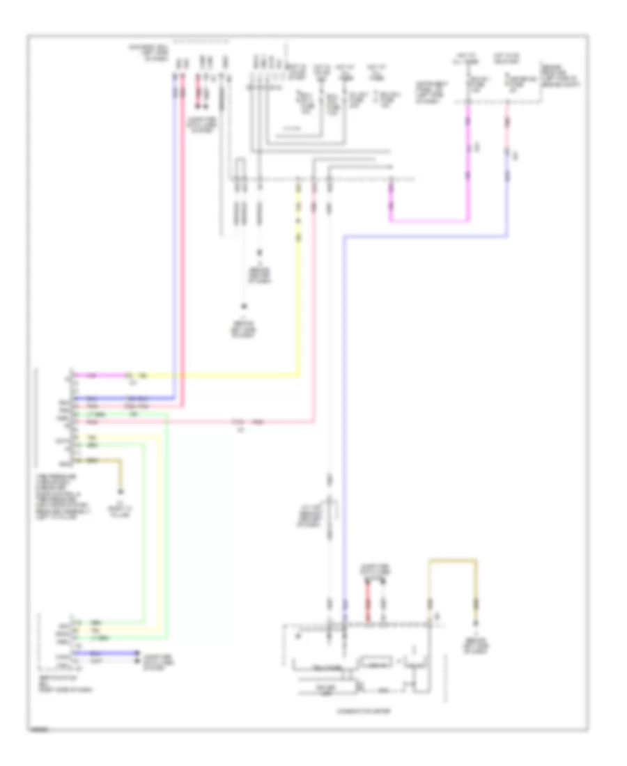
Key Reminder & Seat Belt Warning Wiring Diagram, Except Hybrid for Toyota Camry Hybrid XLE 2014
List of elements for Key Reminder & Seat Belt Warning Wiring Diagram, Except Hybrid for Toyota Camry Hybrid XLE 2014:
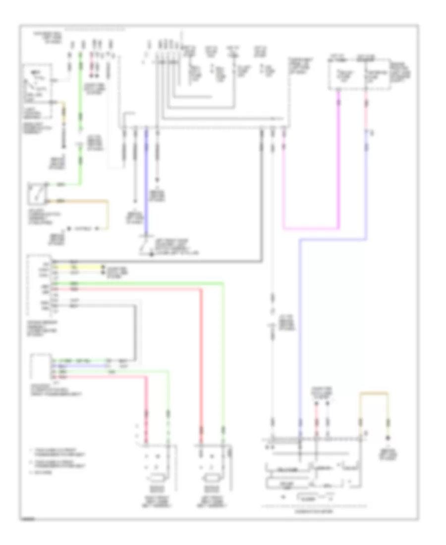

Seat Belt Warning Wiring Diagram, Hybrid for Toyota Camry Hybrid XLE 2014
List of elements for Seat Belt Warning Wiring Diagram, Hybrid for Toyota Camry Hybrid XLE 2014:
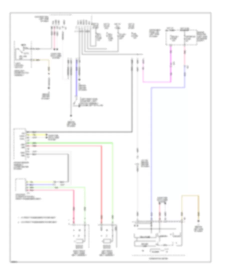
Tire Pressure Monitoring Wiring Diagram, Except Hybrid for Toyota Camry Hybrid XLE 2014
List of elements for Tire Pressure Monitoring Wiring Diagram, Except Hybrid for Toyota Camry Hybrid XLE 2014:
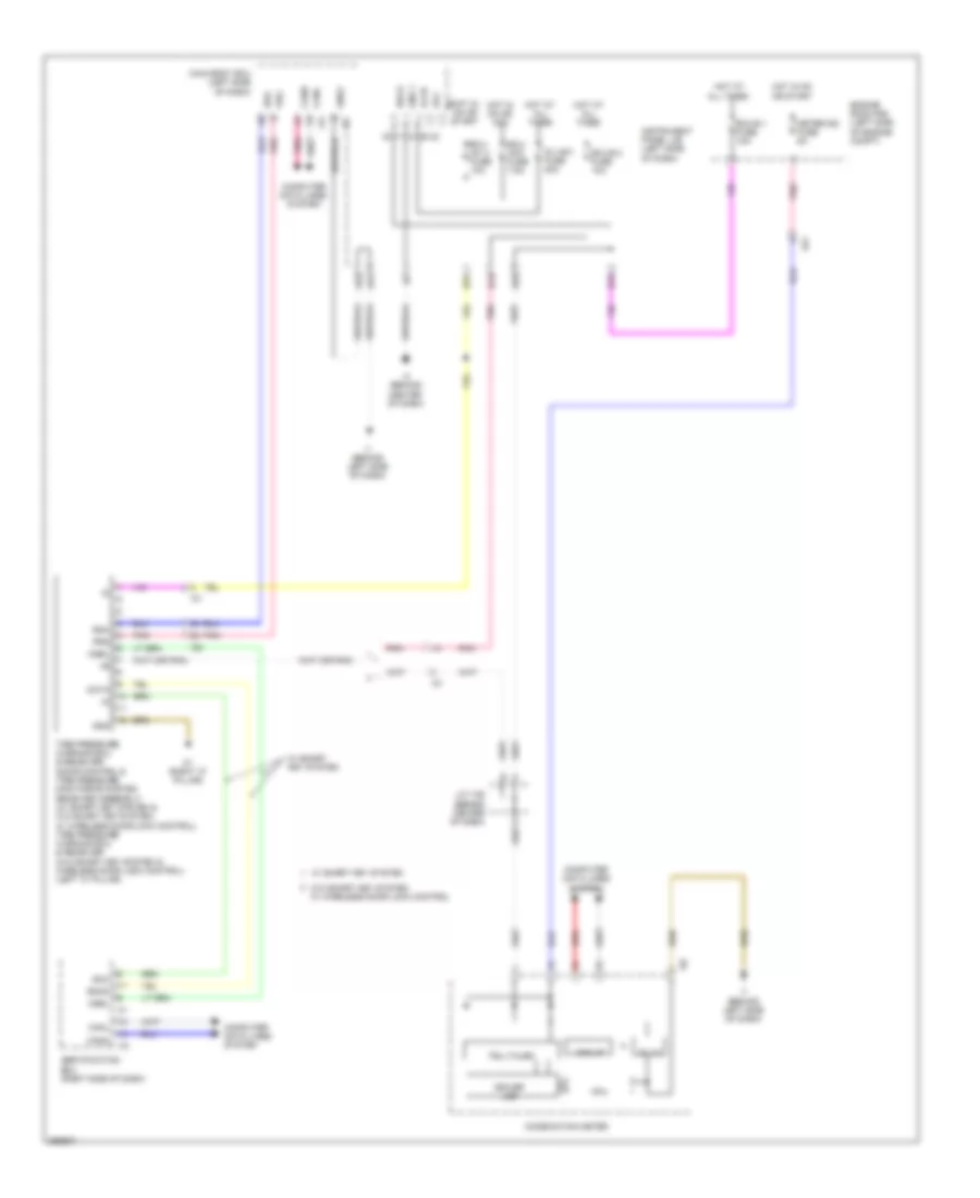
Tire Pressure Monitoring Wiring Diagram, Hybrid for Toyota Camry Hybrid XLE 2014
List of elements for Tire Pressure Monitoring Wiring Diagram, Hybrid for Toyota Camry Hybrid XLE 2014: