POWER DISTRIBUTION
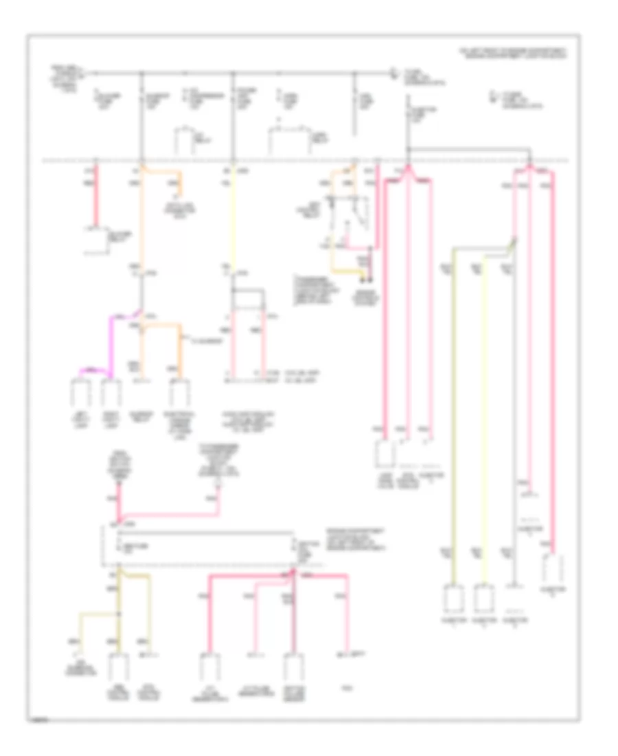
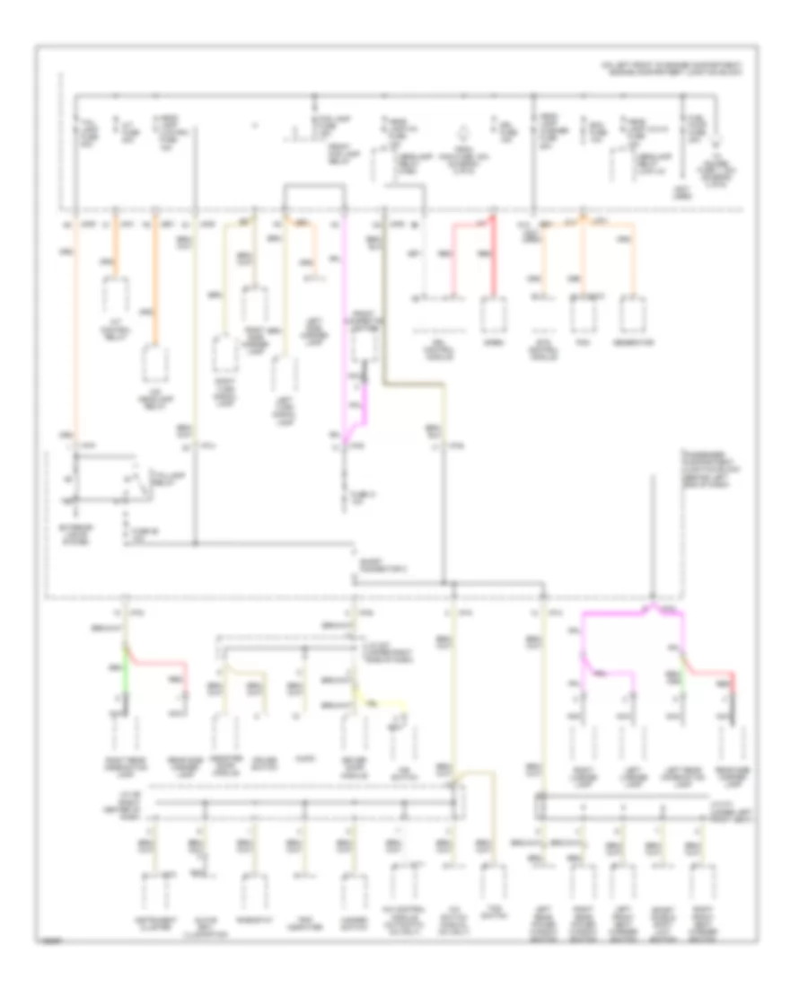
Power Distribution Wiring Diagram (1 of 6) for Hyundai XG350 2004
 https://portal-diagnostov.com/license.html
Automotive Electricians Portal FZCO
Automotive Electricians Portal FZCO
https://portal-diagnostov.com/license.html
https://portal-diagnostov.com/license.html
Automotive Electricians Portal FZCO
Automotive Electricians Portal FZCO
List of elements for Power Distribution Wiring Diagram (1 of 6) for Hyundai XG350 2004:
- (not used)
- (on left front of engine compartment) engine compartment junction block
- 87a
- A/c fan relay 1
- Abs control module
- Abs fusible link 1 30a
- Abs fusible link 2 30a
- Acc
- Accessory socket
- Air bleeding connector
- Ashtray illumination
- Audio
- Battery
- Battery ground
- Burglar alarm relay
- Condenser fusible link 20a
- Driver door module
- Electronic time & alarm control module (etacm)
- Engine compartment junction block (on left front of engine compt)
- Ets control module
- Front cigarette lighter
- Fuse 13 10a
- Fuse 14 10a
- Fuse 15 20a
- Fuse 16 10a
- Fuse 32 10a
- Fusible link 140a
- G03 (on left "a" pillar, near passenger compartment junction block)
- G07 (at left floor panel crossmember)
- Generator
- I/p-a
- I/p-b
- I/p-d
- I/p-e
- I/p-p
- Ignition fusible link 1 30a
- Ignition fusible link 2 30a
- Ignition switch
- Ims control module
- Ims switch
- Interior lights system
- J/c m08 (left center of dash)
- Jc01 b5
- Jco1
- Jm09
- Jm10
- Lock
- M110-1
- M33-3
- Nca
- Off
- Passenger compartment junction block (behind left end of dash)
- Pnk
- Power window fusible link 40a
- Power window relay
- Radiator fan relay
- Radiator fusible link 30a
- Rear accessory socket
- Red
- Rheostat
- Start
- Start motor
- Start relay
- Start solenoid
- To blower fuse, 30a (diagram 2 of 6)
- To engine compartment junction block (abs fuse, 10a) (diagram 2 of 6)
- To passenger compartment junction block (fuse 3, 10a) (diagram 5 of 6)
- Transaxle range switch
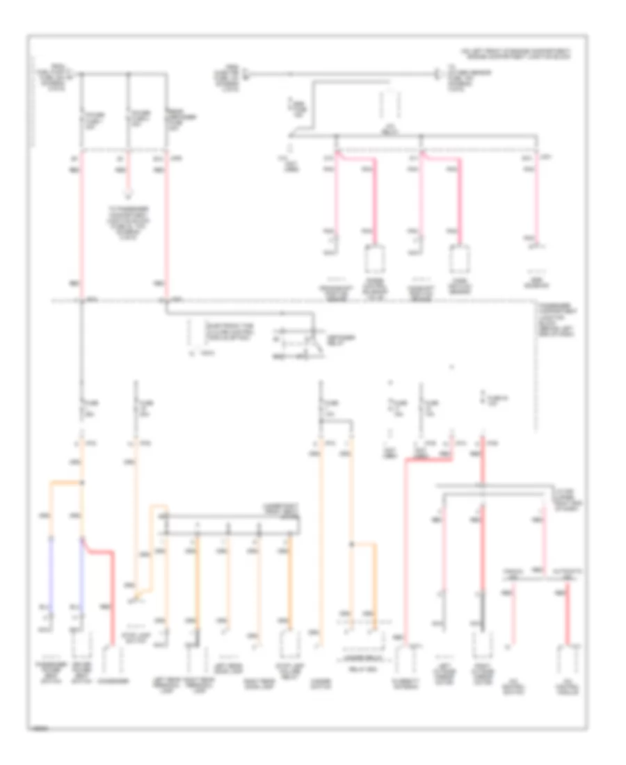
Power Distribution Wiring Diagram (2 of 6) for Hyundai XG350 2004
List of elements for Power Distribution Wiring Diagram (2 of 6) for Hyundai XG350 2004:
- (on left front of engine compartment) engine compartment junction block
- (w/ jbl amp)
- (w/o jbl amp)
- A/c compressor fuse 10a
- A/c relay
- A/t pulse generator-a
- A/t pulse generator-b
- Abs control module
- Abs fuse 10a
- Air bleeding connector
- Audio amp module 2 (w/o jbl amp) audio amp module 1 (w/ jbl amp)
- B10
- Blower fuse 30a
- Blower relay
- C44-3
- D12
- Data link connector (dlc)
- Ecm control relay
- Electrical chrome mirror (w/ home link)
- Engine compartment junction block (on left front of engine compartment)
- Engine controls system
- Ets control module
- F10
- F11
- From abs fusible a link 2, 30a (diagram 1 of 6)
- From ignition switch (diagram 1 of 6)
- Horn fuse 15a
- Horn relay
- I/p-a
- I/p-b
- I/p-e
- I/p-m
- Ignition coil fuse 20a
- Ignition failure sensor
- Injector
- Injector fuse 10a
- Jc01
- Jm09
- Lamp home valve
- Left vanity lamp
- M136
- M137
- Main fuse 30a
- Passenger compartment junction block (behind left end of dash)
- Pcm
- Pnk
- Power amp fuse 20a
- Red
- Right vanity lamp
- Sunroof fuse 15a
- Sunroof relay
- Tan
- To drl fuse, 15a (diagram 6 of 6)
- To egr fuse, 15a (diagram 3 of 6)
- To passenger compartment junction block (fuse 21, 10a) (diagram 4 of 6)
- W/ sunroof
Power Distribution Wiring Diagram (3 of 6) for Hyundai XG350 2004
List of elements for Power Distribution Wiring Diagram (3 of 6) for Hyundai XG350 2004:
- (diagram 6 of 6)
- (not used)
- (on left front of engine compartment) engine compartment junction block
- (under right front seat) j/c m78
- A/c control module
- A/c control switch
- A/c relay
- Automatic a/c
- B12
- C10
- Camshaft position sensor
- Condenser
- Crankshaft position sensor
- D10
- D11
- Defogger relay
- Diversity antenna
- Driver power seat switch
- E10
- Egr fuse 15a
- Egr solenoid
- Electronic time & alarm control module (etacm)
- From fuel pump fuse, 20a h
- From injector fuse, 10a (diagram 2 of 6)
- Fuse 10a
- Fuse 15a
- Fuse 20a
- Fuse 25a
- Fuse 30 10a
- Hazard relay
- Hazard switch
- I/p-a
- I/p-b
- I/p-d
- I/p-e
- I/p-g
- I/p-k
- I/p-p
- I17-1
- J/c m36 (upper right end of dash)
- Jc01
- Jm09
- Left outside mirror motor
- Left rear door lamp
- Left rear personal lamp
- M33-3
- M77-1
- Manual a/c
- Mass air flow sensor
- Nca
- Passenger compartment junction block (behind left end of dash)
- Passenger power seat switch
- Pnk
- Power fuse 1 30a
- Power fuse 2 30a
- Purge control solenoid valve
- Rear defogger fuse 30a
- Red
- Relay box
- Right outside mirror motor
- Right rear door lamp
- Right rear personal lamp
- Stop lamp failure relay
- Stop lamp switch
- To oxygen sensor fuse, 15a (diagram 4 of 6)
- To passenger compartment junction block (fuse 20, 10a) (diagram 5 of 6)
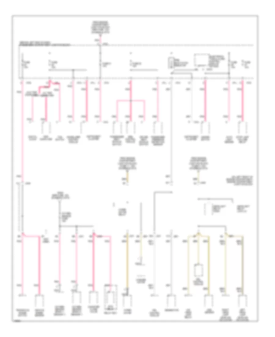
Power Distribution Wiring Diagram (4 of 6) for Hyundai XG350 2004
List of elements for Power Distribution Wiring Diagram (4 of 6) for Hyundai XG350 2004:
- (behind left end of dash) passenger compartment junction block
- (not used)
- (on left front of engine compartment) engine compartment junction block
- (w/ trip computer)
- (w/o trip computer)
- A11
- Aqs sensor
- Auto light sensor
- C12
- Canister close valve
- Digital clock
- Driver seat buckle switch
- Drl control module
- E11
- E12
- Electronic time & alarm control module (etacm)
- Ets relay
- From egr fuse, 15a (diagram 3 of 6)
- From engine compartment junction block (abs fuse, 10a) (diagram 2 of 6)
- From engine compartment junction block, (fuse 11, 15a) (diagram 5 of 6)
- From engine compartment junction block, (fuse 5, 10a) (diagram 5 of 6)
- Fuse 10a
- Fuse 21 10a
- Fuse 22 15a
- Generator
- Hazard switch
- Headlight relay (high)
- Headlight relay (low-lh)
- Hid head lamp relay
- I/p-b
- I/p-d
- I/p-g
- I/p-h
- I/p-j
- I/p-k
- I/p-l
- I18-2
- Immobilizer control module
- Instrument cluster
- Jc01
- Jc01 a6
- Je01
- Jm09
- Left head lamp leveling actuator
- M33-3
- Nca
- Oxygen sensor (bank 1/ sensor 1)
- Oxygen sensor (bank 2/ sensor 1)
- Oxygen sensor fuse 15a
- Passenger presence detection sensor
- Passenger seat buckle switch
- Pnk
- Pre- excitation resistor
- Relay box
- Right head lamp leveling actuator
- Srs control module
- Stop lamp failure relay
- Tcs switch
- Transaxle range switch
- Trip computer
- Vehicle speed sensor
- Washer motor
- Wiper motor
- Wiper motor relay
Power Distribution Wiring Diagram (5 of 6) for Hyundai XG350 2004
List of elements for Power Distribution Wiring Diagram (5 of 6) for Hyundai XG350 2004:
- (behind left end of dash) passenger compartment junction block
- (left center of dash) j/c i20
- (not used)
- (w/o home link) (w/ home link)
- A/c control module
- A/c control module (automatic a/c)
- A/c switch
- A/c switch (manual a/c)
- Assister door module
- Audio
- Auto headlamp levelling sensor
- Auto- matic a/c
- Automatic a/c manual a/c
- Blower relay
- Cruise switch
- Digital clock
- Door warning & ignition key illumination
- Driver door module
- Electrical chrome mirror (w/ home link)
- Electrical control mirror
- Electronic power steering control module
- Electronic time & alarm control module (etacm)
- Ets relay
- From engine compartment junction block, power fuse 2, 30a (diagram 3 of 6)
- From ignition switch (diagram 1 of 6)
- Fuel filler door & trunk lid switch
- Fuse 10a
- Fuse 15a
- Fuse 20 10a
- Fuse 20a
- Fuse 24 20a
- Fuse 25 10a
- Fuse 4 15a
- I/p-a
- I/p-d
- I/p-e
- I/p-g
- I/p-h
- I/p-j
- I/p-k
- I/p-m
- I/p-p
- I17-1
- I18-1
- I18-2
- Immobilizer control module
- Ims control module
- Instrument cluster
- Left foot lamp
- Left front door lamp
- Left front seat warmer switch
- Left trunk room lamp
- M110-4
- M33-3
- Manual a/c
- Map lamp
- Mode actuator
- Multipurpose check connector
- Nca
- Overhead console lamp
- Rain sensor
- Rain sensor relay
- Red
- Relay box
- Right foot lamp
- Right front door lamp
- Right front seat warmer switch
- Right trunk room lamp
- Room lamp
- Short connector "b"
- Short connector a
- Sunroof relay
- Tempe- rature switch
- To engine compartment junction block, headlight relay (high) (diagram 4 of 6)
- To engine compartment junction block, wiper motor relay (diagram 4 of 6)
- Trip computer
- Trunk lid relay
- Trunk lid solenoid
- W/ sunroof
- W/ trip computer
- W/o sunroof
- W/o trip computer
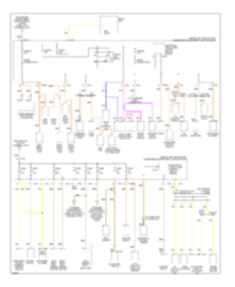
Power Distribution Wiring Diagram (6 of 6) for Hyundai XG350 2004
List of elements for Power Distribution Wiring Diagram (6 of 6) for Hyundai XG350 2004:
- (not used)
- (on left front of engine compartment) engine compartment junction block
- A/c control module (automatic a/c only)
- A/c switch (manual a/c only)
- A/t control relay
- A/t fuse 20a
- Assister door module
- Audio
- C11
- C44-2
- Cruise switch
- Driver door module
- Drl control module
- Drl fuse 15a
- Ecm fuse 10a
- Ets control module
- Exterior lights system
- Fog lamp fuse 15a
- From main fuse, 30a (diagram 2 of 6)
- Front cigarette lighter
- Front fog lamp relay
- Fuel pump fuse 20a
- Fuse 26 10a
- Fuse 31 10a
- Generator
- Glove box illumination
- Hazard switch
- Head lamp (hi) fuse 15a
- Head lamp (lo-lh) fuse 15a
- Head lamp (low-rh) fuse 15a
- Head lamp washer fuse 20a
- Headlamp relay (high)
- Headlamp relay (low-lh)
- Hid headlamp relay
- I/p-a
- I/p-b
- I/p-d
- I/p-e
- I/p-h
- I/p-k
- I/p-p
- I17-1
- I18-2
- Ims switch
- Instrument cluster
- J/c i29 (right center of dash)
- J/c m37 (upper right side of dash)
- J/c m71 (under left front seat)
- Jc01
- Je01
- Je01 d12
- Jm09
- Jm09 c8
- Left front seat warmer switch
- Left license lamp
- Left rear combination lamp
- Left rear power window switch
- Left side marker lamp
- Left turn signal lamp
- Nca
- Passenger compartment junction block (behind left end of dash)
- Pcm
- Rear side marker lamp
- Red
- Rheostat
- Right front seat warmer switch
- Right license lamp
- Right rear combination lamp
- Right rear power window switch
- Right side marker lamp
- Right turn signal lamp
- Short connector c
- Siren
- Sport mode & shift limit switch
- Tail lamp fuse 20a
- Taillamp relay
- Tcs switch
- To power fuse 1, 30a (diagram 3 of 6)
- Trip computer

 Čeština
 Dansk
Dansk Deutsch
 Ελληνικά
 English
 English
 Español
 Suomi
Suomi Français
 Français
 עברית
עברית Hrvatski
 Magyar
 Italiano
 日本語
日本語 한국어
한국어 Nederlands
 Polski
 Português
 Română
 Русский
 Slovenčina
 Slovenščina
 Svenska
 Türkçe
 中文 (中国)