ENGINE PERFORMANCE
2.8L
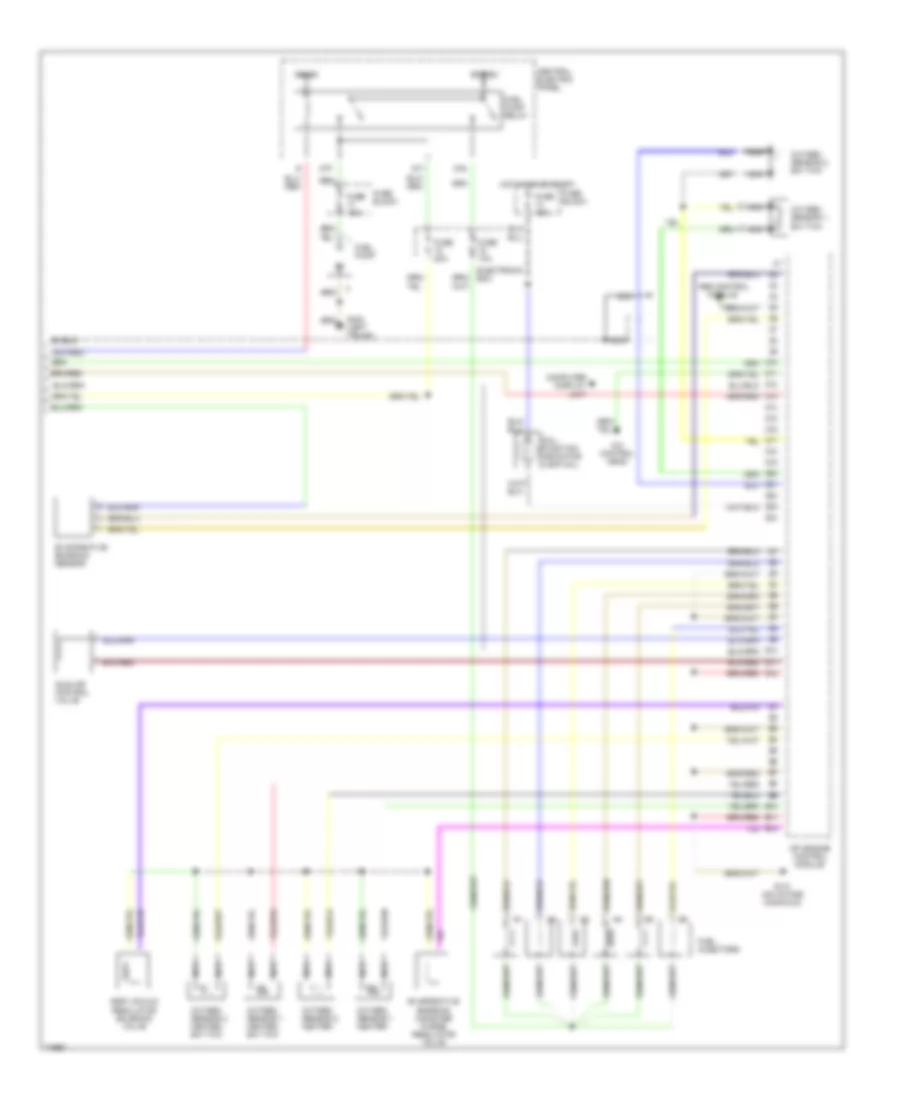
2.8L, Wiring Diagram (A6 2.8L Wiring Diagram Early Production 1 Of 2) for Audi A6 1995
 https://portal-diagnostov.com/license.html
Automotive Electricians Portal FZCO
Automotive Electricians Portal FZCO
https://portal-diagnostov.com/license.html
https://portal-diagnostov.com/license.html
Automotive Electricians Portal FZCO
Automotive Electricians Portal FZCO
List of elements for 2.8L, Wiring Diagram (A6 2.8L Wiring Diagram Early Production 1 Of 2) for Audi A6 1995:
- (on intake manifold)
- (right i/p)
- (speedometer)
- (tachometer)
- A10
- A11
- A12
- A13
- A14
- A15
- A16
- A17
- A18
- A19
- A20
- A21
- A22
- A23
- A24
- B10
- B11
- B12
- B16
- Bat(30)
- Camshaft position sensor
- Central electric panel
- Closed throttle position switch/ throttle position sensor
- Crankshaft position sensor
- Data link connector (behind console)
- Data link connector (rapid data transfer)
- Egr temperature sensor
- Electronic box
- Engine coolant temperature sensor
- Engine speed sensor
- Fuse 15a
- G131
- G131 (on intake manifold)
- G201
- G900 (left a pillar)
- Ign (15)
- Ignition coil 1
- Ignition coil 2
- Ignition coil 3
- Instrument cluster
- Instrument cluster combination processor
- Intake manifold change- over valve
- Knock sensor #1
- Knock sensor #2
- Mass air flow sensor
- Mfi engine control module
- Nca
- Oxygen sensor
- Power output stage
- Red
- Shield
- Solid state
- Spark plugs 1 & 6
- Spark plugs 2 & 4
- Spark plugs 3 & 5
- Speedo- meter vehicle speed sensor
- T26
- T26a
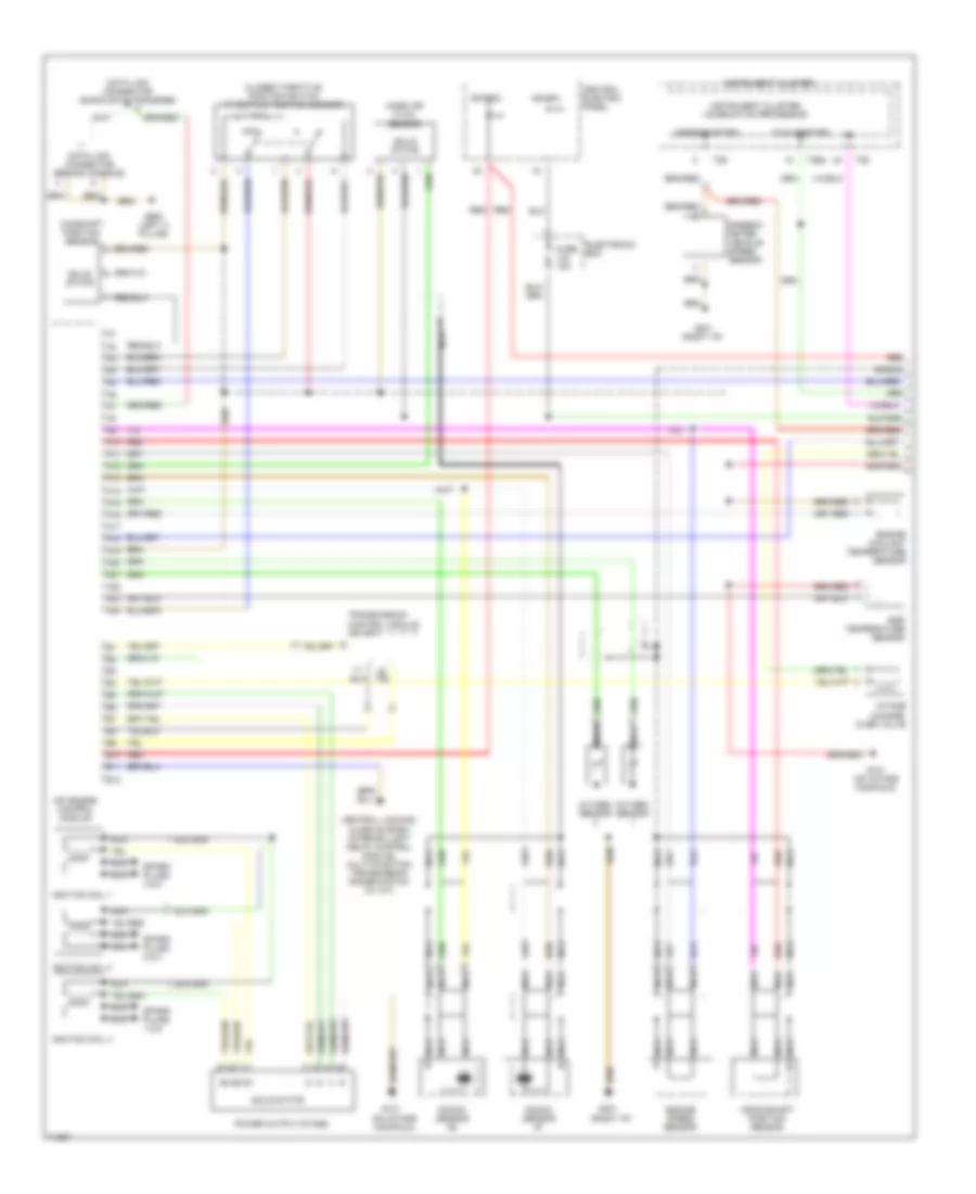
2.8L, Wiring Diagram (A6 2.8L Wiring Diagram Early Production 2 Of 2) for Audi A6 1995
List of elements for 2.8L, Wiring Diagram (A6 2.8L Wiring Diagram Early Production 2 Of 2) for Audi A6 1995:
- 87f
- 87a
- A/c control head
- Abs control
- Bat(30)
- C1
- C10
- C11
- C12
- C13
- C14
- C15
- C16
- C17
- C18
- C19
- C20
- C21
- C22
- C23
- C24
- Central electric panel
- Computer display
- D10
- D11
- D12
- Dti
- E10
- E11
- E12
- Egr vacuum regulator solenoid valve
- Electronic box
- Evaporative emission canister purge regulator valve
- Evaporative emission sensor
- Fuel injectors
- Fuel pump
- Fuel pump relay
- Fuse 10a
- Fuse 15a
- Fuse 20a
- Fuse block
- G131 (on intake manifold)
- G404 (left trunk)
- Hot in on or start
- Idle air control valve
- Ign(15)
- Mal- function indicator lamp (mil)
- Mfi engine control module
- Module
- Nca
- Oxygen sensor 1 heater
- Oxygen sensor 1 heater, b/h twc
- Oxygen sensor 1, b/h twc
- Oxygen sensor 2 heater
- Oxygen sensor 2 heater, b/h twc
- Oxygen sensor 2, b/h twc
- Shield
- Unit
2.8L, Wiring Diagram (A6 2.8L Wiring Diagram Late Production 1 Of 2) for Audi A6 1995
List of elements for 2.8L, Wiring Diagram (A6 2.8L Wiring Diagram Late Production 1 Of 2) for Audi A6 1995:
- (on intake manifold)
- (right i/p)
- (speedometer)
- (tachometer)
- A10
- A11
- A12
- A13
- A14
- A15
- A16
- A17
- A18
- A19
- A20
- A21
- A22
- A23
- A24
- B10
- B11
- B12
- Bat(30)
- Camshaft position sensor
- Central electric panel
- Central locking/ alarm system/ interior light delay control module, multi-function transmission range switch (w/ a/t)
- Closed throttle position switch (throttle position sensor)
- Crankshaft position sensor
- Data link connector (behind console)
- Data link connector (rapid data transfer)
- Egr temperature sensor
- Electronic box
- Engine coolant temperature sensor
- Engine speed sensor
- Fuse 15a
- G131
- G131 (on intake manifold)
- G201
- G900 (left a pillar)
- Ign (15)
- Ignition coil 1
- Ignition coil 2
- Ignition coil 3
- Instrument cluster
- Instrument cluster combination processor
- Intake change- over valve
- Knock sensor #1
- Knock sensor #2
- Mass air flow sensor
- Mfi engine control module
- Nca
- Oxygen sensor
- Power output stage
- Red
- Shield
- Solid state
- Spark plugs 1 & 6
- Spark plugs 2 & 4
- Spark plugs 3 & 5
- Speedo- meter vehicle speed sensor
- T26
- T26a
- Transmission control module (w/ a/t)
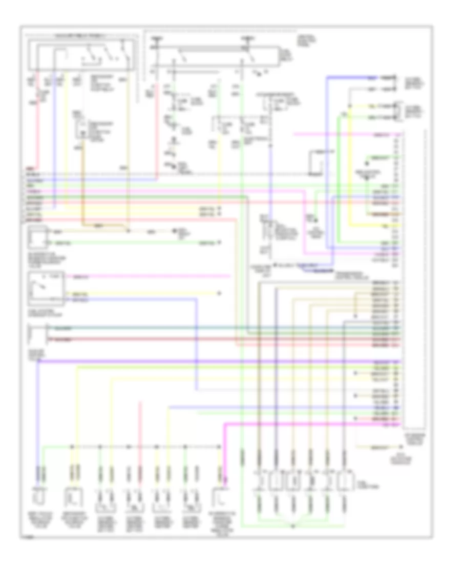
2.8L, Wiring Diagram (A6 2.8L Wiring Diagram Late Production 2 Of 2) for Audi A6 1995
List of elements for 2.8L, Wiring Diagram (A6 2.8L Wiring Diagram Late Production 2 Of 2) for Audi A6 1995:
- 87f
- 87a
- A/c control head
- Abs control
- Auxiliary relay panel 3
- Bat(30)
- C1
- C10
- C11
- C12
- C13
- C14
- C15
- C16
- C17
- C18
- C19
- C20
- C21
- C22
- C23
- C24
- Central electric panel
- Computer display
- D10
- D11
- D12
- Dti
- E10
- E11
- E12
- Egr vacuum regulator solenoid valve
- Electronic box
- Evaporative emission canister purge regulator valve
- Evaporative emission canister purge solenoid valve
- Fuel injectors
- Fuel pump
- Fuel pump relay
- Fuel system diagnostic pump
- Fuse 10a
- Fuse 15a
- Fuse 20a
- Fuse 40a
- Fuse block
- G131 (on intake manifold)
- G201 (right i/p)
- G404 (left trunk)
- Hot in on or start
- Idle air control valve
- Ign(15)
- Mal- function indicator lamp (mil)
- Mfi engine control module
- Module
- Nca
- Oxygen sensor 1 heater
- Oxygen sensor 1 heater, b/h twc
- Oxygen sensor 1, b/h twc
- Oxygen sensor 2 heater
- Oxygen sensor 2 heater, b/h twc
- Oxygen sensor 2, b/h twc
- Red
- Secondary air injection pump motor
- Secondary air injection pump relay
- Secondary air injection solenoid valve
- Shield
- Transmission control module
- Unit

 Čeština
 Dansk
Dansk Deutsch
 Ελληνικά
 English
 English
 Español
 Suomi
Suomi Français
 Français
 עברית
עברית Hrvatski
 Magyar
 Italiano
 日本語
日本語 한국어
한국어 Nederlands
 Polski
 Português
 Română
 Русский
 Slovenčina
 Slovenščina
 Svenska
 Türkçe
 中文 (中国)