SHIFT INTERLOCK
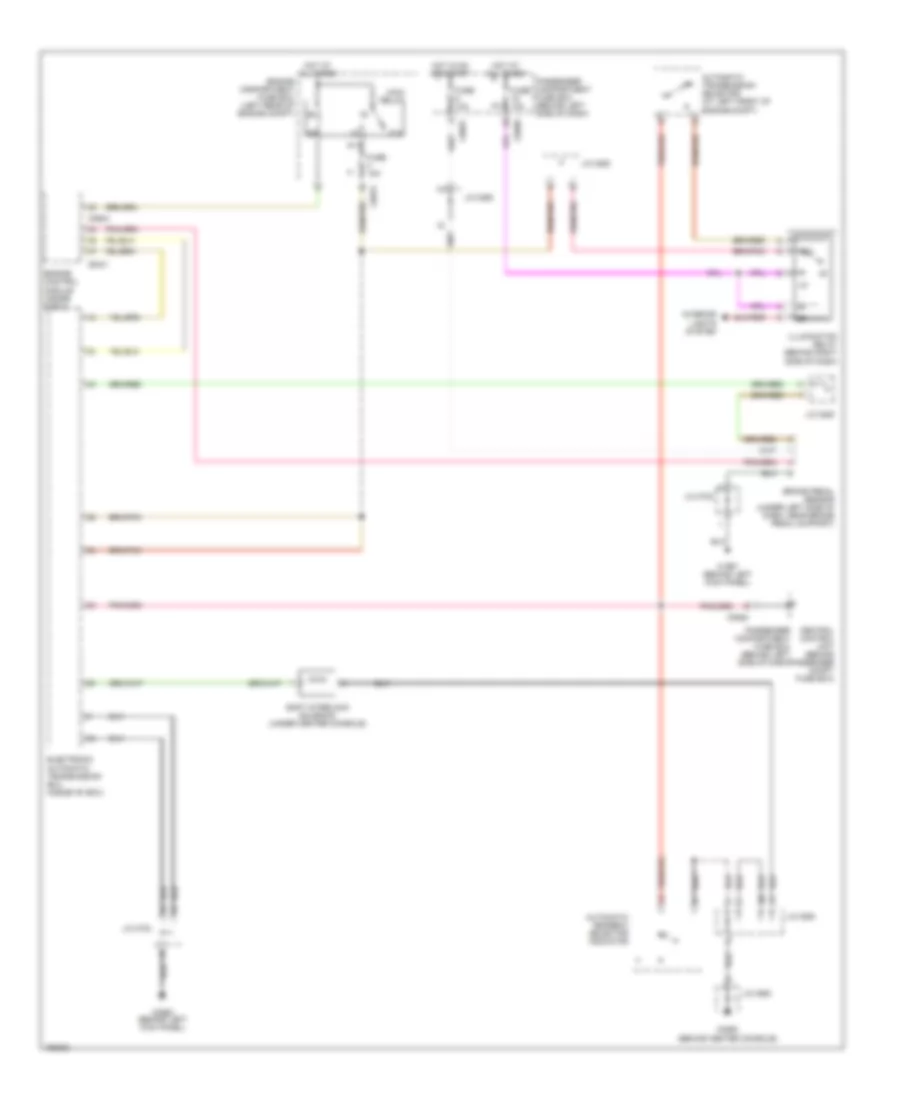
Shift Interlock Wiring Diagram for Land Rover Freelander SE3 2005
List of elements for Shift Interlock Wiring Diagram for Land Rover Freelander SE3 2005:
- (behind center console)
- 87a
- Automatic gearbox selector indicator
- Automatic transmission selector (at left front of engine compt)
- Brake pedal sensor (under left side of dash, near brake pedal support)
- C0331
- C0550
- C0562 (behind left kick panel)
- C0575
- C0581
- C0582
- C0589
- C0604
- C1967 (behind left kick panel)
- Central control unit (behind passenger compt fuse box)
- Electronic automatic transmission ecu (inside "e" box)
- Engine compartment fuse box (left rear of engine compt)
- Engine control module (inside e-box)
- Fuse 10a
- Fuse 15a
- Hot at all times
- Hot in on or start
- Illumination relay (behind right side of dash)
- Interior lights system
- J/c 0285
- J/c 0292
- J/c 0294
- J/c 0550
- J/c 0723
- Main relay
- Passenger compartment fuse box (behind left side of dash)
- Shift interlock solenoid (under center console)
 Čeština
 Dansk
Dansk Deutsch
 Ελληνικά
 English
 English
 Español
 Suomi
Suomi Français
 Français
 עברית
עברית Hrvatski
 Magyar
 Italiano
 日本語
日本語 한국어
한국어 Nederlands
 Polski
 Português
 Română
 Русский
 Slovenčina
 Slovenščina
 Svenska
 Türkçe
 中文 (中国)
 Português