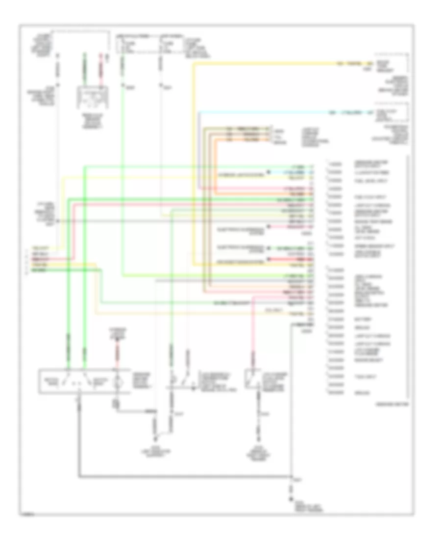
INSTRUMENT CLUSTER
Instrument Cluster Wiring Diagram (1 of 2) for Ford Explorer 1998
 https://portal-diagnostov.com/license.html
Automotive Electricians Portal FZCO
Automotive Electricians Portal FZCO
https://portal-diagnostov.com/license.html
https://portal-diagnostov.com/license.html
Automotive Electricians Portal FZCO
Automotive Electricians Portal FZCO
List of elements for Instrument Cluster Wiring Diagram (1 of 2) for Ford Explorer 1998:
- "anti-theft" indicator
- "brake" indicator
- "door ajar" indicator
- "fasten seatbelt" indicator
- (4.0l ohv & 5.0l)
- (4.ol sohc)
- (center of dash) s274
- (eng compt harn, near a/c relay)
- (eng compt harn, near gem) s275
- (i/p harn, near breakout to inst cluster)
- 4.0l ohv & 5.0l
- 4.0l sohc
- 4wd indicator (hi-range)
- 4wd indicator (lo-range)
- Acc
- Air bag indicator
- Anti-lock brakes system
- Anti-lock indicator
- Anti-theft system
- Brake fluid level warning switch (mounted on low left side of master cylinder)
- C286
- C287
- C288
- Charge indicator
- Check gauge
- Cruise control system
- Daytime running lamps (drl) module (left front corner of eng compt)
- Dc out
- Dimmer module (left side of steering column)
- Dimmer relay (in relay module, behind center of dash)
- Engine controls system
- Engine coolant temperature gauge
- Engine coolant temperature sender (behind gen bracket)
- Engine oil pressure gauge
- Engine oil pressure switch (on engine, next to power steering pump)
- Exterior lights system
- Fuel guage
- Fuel reset switch indicator
- Fuel tank assembly
- Fuse 15a
- Fuse 7.5a
- G104 (rear of left front fender)
- G108 (left radiator support)
- Head
- Headlamp switch
- Headlights system
- Hi beam
- Hot at all times
- Hot in run or start
- I/p fuse panel (left side of vehicle, below dash)
- Ignition switch
- Illumination lamps
- Instrument cluster
- Interior lights system
- Left turn
- Lock
- Malfunction indicator lamp
- Off
- Park
- Parking brake switch (on right side of parking brake lever)
- Right turn
- Run
- S104
- S128
- S154
- S176 (eng compt harn, near breakout to brk press switch)
- S213
- S228
- S229
- S232
- S234
- S242
- S264
- S276
- Slosh module
- Speed control indicator
- Speedometer/ odometer
- Start
- Starting/charging system
- Tachometer
- Tachometer data link connector (right rear corner of engine compt)
- Transmission control indicator (tcil)
- Voltmeter
- W/ drl
- W/o drl
- Warning system
- Warning systems
Instrument Cluster Wiring Diagram (2 of 2) for Ford Explorer 1998
List of elements for Instrument Cluster Wiring Diagram (2 of 2) for Ford Explorer 1998:
- (arc) disable switch input
- (arc) warning input oil temp/ level sense english/metric output (gem) to message center
- (i/p harn, near breakout to instr cluster) s247
- 1/c2008
- 10/c2008
- 11/c2008
- 12/c2008
- 2/c2008
- 21/c2009
- 22/c2009
- 23/c2009
- 24/c2009
- 25/c2009
- 26/c2009
- 27/c2009
- 28/c2009
- 29/c2009
- 3/c2008
- 30/c2009
- 31/c2009
- 32/c2009
- 33/c2009
- 34/c2009
- 35/c2009
- 36/c2009
- 4/c2008
- 4wabs control module (left side of engine compt)
- 5.0l only
- 5/c2008
- 6/c2008
- 7/c2008
- 8/c2008
- 9/c2008
- Air conditioning system
- Battery
- Brake
- C186
- C2008
- C2009
- C280
- Electronic suspension system
- Engine select
- Engine temp sense
- Fuel flow input
- Fuel flow rate output
- Fuel level input
- Fuse 7.5a
- G104 (rear of left front fender)
- G105 (rear of right front fender)
- G108 (left radiator support)
- Generic electronic module (behind center of dash)
- Ground
- Head
- Hot at all times
- Hot in run
- I/p fuse panel (left side of vehicle, below dash)
- Illumination feed
- Interior lights system
- Lamp out warning
- Lamp out warning module (in dash panel console)
- Low engine oil/ temperature switch (left side of engine, on oil pan)
- Low washer fluid level switch (in washer reservoir)
- Low washer fluid sense
- Message center
- Message center switch assembly
- Message center switch input
- Oil temp/ level sense
- Powertrain control module (mounted through firewall)
- Rear axle sensor (on axle assembly)
- Red
- Red/pnk
- S137
- S161
- S168 (engine compt harn, near 4wabs ctrl module)
- S209
- S231
- S233
- S241
- Sound tone request
- Speed sensor input
- Switch bank
- Tach input
- Tail
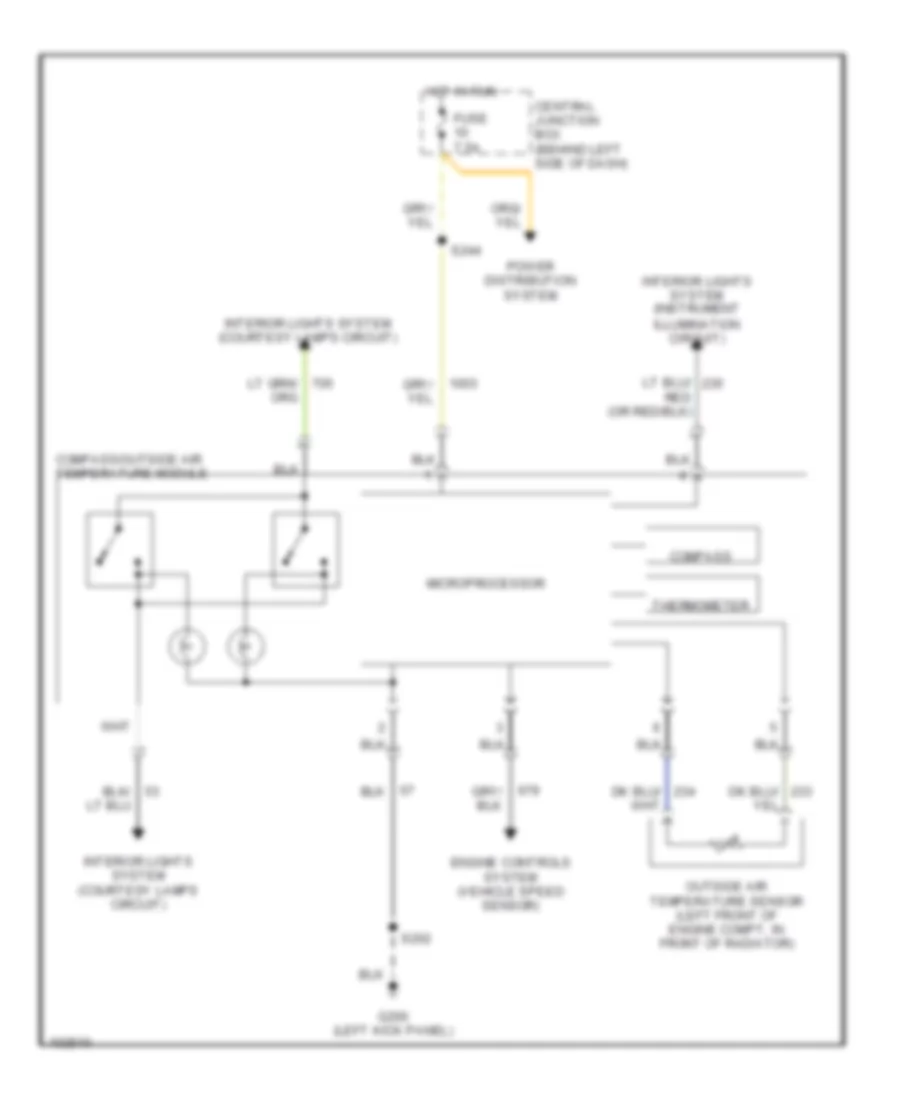
Overhead Console Wiring Diagram for Ford Explorer 1998
List of elements for Overhead Console Wiring Diagram for Ford Explorer 1998:
- Central junction box (behind left side of dash)
- Compass
- Compass/outside air temperature module
- Engine controls system (vehicle speed sensor)
- Fuse 7.5a
- G200 (left kick panel)
- Hot in run
- Interior lights system (courtesy lamps circuit)
- Interior lights system (instrument illumination circuit)
- Microprocessor
- Outside air temperature sensor (left front of engine compt, in front of radiator)
- Power distribution system
- S202
- S244
- Thermometer

 Čeština
 Dansk
Dansk Deutsch
 Ελληνικά
 English
 English
 Español
 Suomi
Suomi Français
 Français
 עברית
עברית Hrvatski
 Magyar
 Italiano
 日本語
日本語 한국어
한국어 Nederlands
 Polski
 Português
 Română
 Русский
 Slovenčina
 Slovenščina
 Svenska
 Türkçe
 中文 (中国)