ANTI-LOCK BRAKES
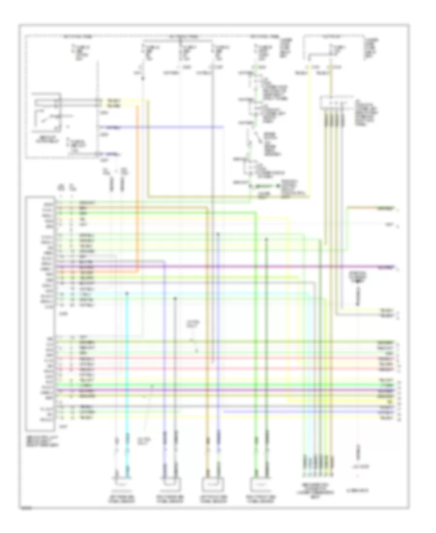
Anti-Lock Brakes Wiring Diagram (1 of 2) for Acura Legend L 1995
List of elements for Anti-Lock Brakes Wiring Diagram (1 of 2) for Acura Legend L 1995:
- (on brake pedal bracket)
- (w/ tcs only)
- +b1
- +b2
- +b3
- 4
- 7.5a
- Abs control unit (behind right side of rear seat)
- Abs inspection connector (under passenger's seat)
- Abs pump motor relay
- Alternator
- Brake switch
- C129
- C191
- C204
- C205
- C207
- C208
- C315
- C406
- C407
- Chg
- Com(-)
- Coupe only
- Fl-in
- Fl-out
- Flp
- Flw(+)
- Flw(-)
- Fr-in
- Fr-out
- Frp
- Frw(+)
- Frw(-)
- Fsr
- Fuse 3 15a
- Fuse 32 abs motor 50a
- Fuse 38 abs unit
- Fuse 39 stop, horn 20a
- Fuse 41 abs b1 15a
- Fuse 42 abs b2 15a
- Fuse 43 abs b3 15a
- Hot at all times
- Hot at all times under- hood fuse/ relay box
- Hot in on
- Ig2
- J/c c200 (under-hood relay box "b", near right strut tower)
- J/c c326/c331 (under left side of dash)
- J/c c326/c379 (under left side of dash or behind right kick panel)
- J/c c348 (under middle of dash)
- Left front abs wheel sensor
- Left rear abs wheel sensor
- Mck
- Park
- Pmp
- Psw
- R-in
- R-out
- Right front abs wheel sensor
- Right rear abs wheel sensor
- Rlp
- Rlw(+)
- Rlw(-)
- Rrp
- Rrw(+)
- Rrw(-)
- Scs
- Starting/ charging system
- Stop
- Traction control circuit (tcs control unit)
- Under- dash fuse/ relay box
- W/ tcs
- W/o tcs
- Warn 1
- Warn 2
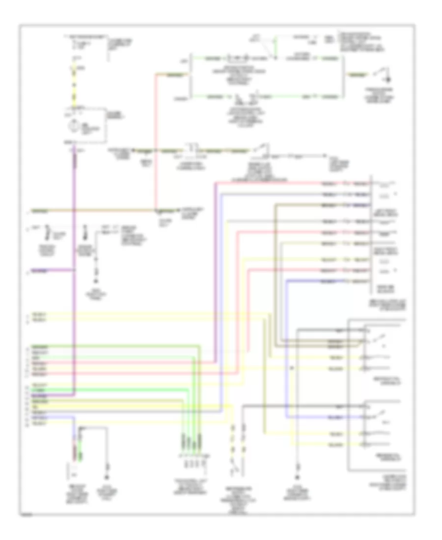
Anti-Lock Brakes Wiring Diagram (2 of 2) for Acura Legend L 1995
List of elements for Anti-Lock Brakes Wiring Diagram (2 of 2) for Acura Legend L 1995:
- (m/t only)
- Abs front fail- safe relay
- Abs indicator light
- Abs modulator unit (right rear corner of eng compt)
- Abs pressure switch (closed with pressure built up) (on right side of fire wall)
- Abs pump motor (right rear corner of eng compt.)
- Abs rear fail- safe relay
- B. ind. ctrl.
- Brake fluid level switch (closed with low fluid level) (in brake fluid reservoir cap)
- C191
- C295
- C317
- C424
- C511
- Canada
- Coupe only
- D10
- D16
- Daytime running lights control unit (behind dash, right of steering column)
- Driving position memory system (dpms) control unit (in luggage compt., on back rest of rear seat)
- Driving position memory system (dpms) diode (m/t only) (behind right kick panel)
- Engine controls system
- Flp
- Frp
- Fuse 13 7.5a
- G104 (left rear of engine compt.)
- G105 (right rear corner of engine compt.)
- G123 (right side of safety wall)
- G203 (right kick panel)
- Gauges assembly
- Hot in on or start
- Instrument cluster system
- Left front abs solenoid
- P.b. in- put
- Park input
- Parking brake switch (at base of park brake lever)
- Rear abs solenoid
- Right front abs solenoid
- Rlp
- Rrp
- Sedan only
- Service check connector (behind right kick panel)
- Tcs control unit (w/ tcs only) (behind right side of rear seat)
- Traction control circuit
- Under-dash fuse/relay box
- Under-hood relay box c (right rear corner of eng compt.)
- Usa
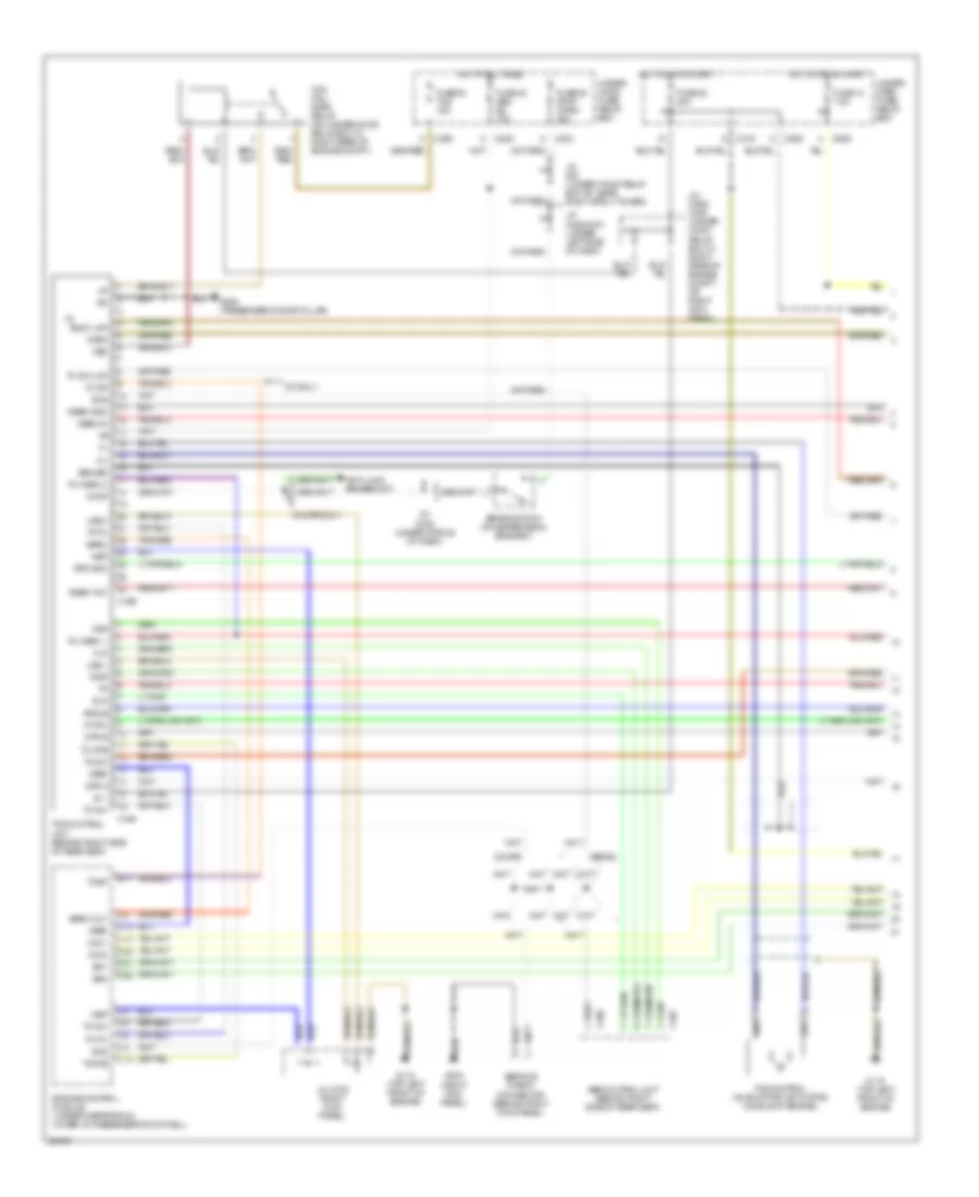
Traction Control Wiring Diagram (1 of 2) for Acura Legend L 1995
List of elements for Traction Control Wiring Diagram (1 of 2) for Acura Legend L 1995:
- A/t only
- Abs control unit (behind right side of rear seat)
- Angle
- Anti-lock brakes ckt.
- Baro
- Baro out
- Brake switch (on brake pedal bracket)
- Busy lmp
- C12
- C204
- C208
- C209
- C316
- C406
- C407
- C424
- C425
- C506
- Coupe
- Coupe only
- D18
- D19
- D20
- D21
- D22
- E11
- Engine control module (under carpeting & cover, in passenger's footwell)
- Flp
- Frp
- Fsr
- Fuse 13 7.5a
- Fuse 22 20a
- Fuse 39 stop, horn 20a
- Fuse 42 abs b2 15a
- Fuse 53 tcs 15a
- G110 (top left front of engine)
- G203 (right kick panel)
- G305 (passenger's door pillar)
- Gsen gnd
- Gsen in
- Gsen vcc
- Hot at all times
- Hot in on or start
- Ig 1
- J/c (under-hood relay box "b", near right strut tower)
- J/c c326/c331 (under left side of dash)
- J/c c348 (under middle of dash)
- J/c c362/ c420 (under hood relay box "c", right rear of engine compt. or right kick panel)
- J/c c379 (right kick panel)
- Lge 1
- Lge 2
- Nep
- Nt sw
- Park
- Rlp
- Rrp
- Scs
- Sealed
- Sedan
- Service check connector (behind right kick panel)
- Sg1
- Sg2
- Stop
- Str a
- Str b
- Str gnd
- Tc fc
- Tc inh
- Tc sp
- Tc stb
- Tc sw
- Tc sw lmp
- Tc warn 1
- Tc warn 2
- Tcs control unit (behind right side of rear seat)
- Tcs control valve motor (actuator) (middle of engine)
- Tcs fail- safe relay (on under-hood relay box "c", right rear of engine compt.)
- Tcsp
- Tcstb
- Tf fc
- Under- dash fuse/ relay box
- Under- hood fuse/ relay box
- Vcc1
- Vcc2
- Vref
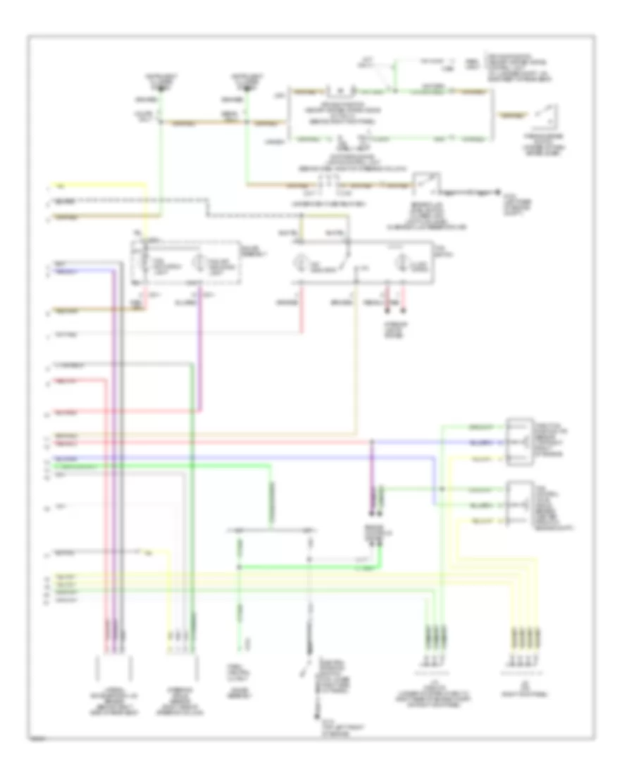
Traction Control Wiring Diagram (2 of 2) for Acura Legend L 1995
List of elements for Traction Control Wiring Diagram (2 of 2) for Acura Legend L 1995:
- "on" indicator
- (m/t only)
- A/t
- B. ind. ctrl.
- Brake fluid level switch (closed with low fluid level) (in brake fluid reservoir cap)
- C191
- C295
- C317
- C511
- C514
- Canada
- Coupe only
- D10
- D18
- Daytime running lights control unit (behind dash, right of steering column)
- Driving position memory system (dpms) control unit (in luggage compt., on back rest of rear seat)
- Driving position memory system (dpms) diode (m/t only) (behind right kick panel)
- Engine controls system
- G104 (left rear of engine compt.)
- G110 (top left front of engine)
- Gauge assembly
- Illumi- nation
- Instrument cluster system
- Interior lights system
- J/c (right kick panel)
- J/c c362/379 (under-hood relay box "c"; right rear of engine compt., or right kick panel)
- Lateral acceleration (lg) sensor (behind right side of rear seat)
- M/t
- Nca
- Neutral position switch (on lower right side of trans.)
- P.b. in- put
- Park input
- Park/ neutral output
- Parking brake switch (at base of park brake lever)
- Red
- Sedan only
- Steering angle sensor (right side of steering column)
- Tcs activation light
- Tcs control valve angle sensor (center front of engine compt.)
- Tcs off indicator light
- Tcs switch
- Throttle position (tp) sensor (top right front of engine)
- Under-dash fuse relay box
- Usa

 Čeština
 Dansk
Dansk Deutsch
 Ελληνικά
 English
 English
 Español
 Suomi
Suomi Français
 Français
 עברית
עברית Hrvatski
 Magyar
 Italiano
 日本語
日本語 한국어
한국어 Nederlands
 Polski
 Português
 Română
 Русский
 Slovenčina
 Slovenščina
 Svenska
 Türkçe
 中文 (中国)