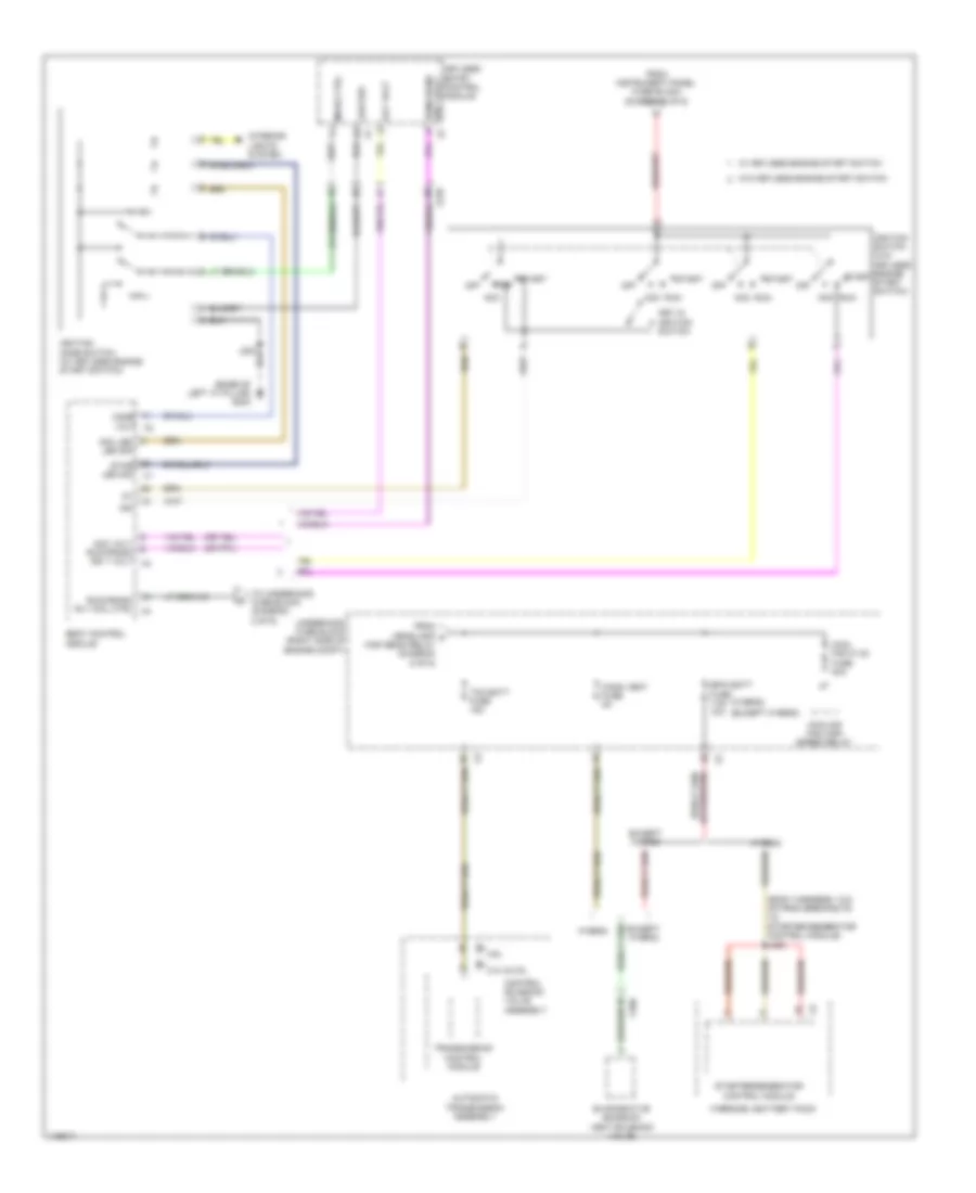
POWER DISTRIBUTION
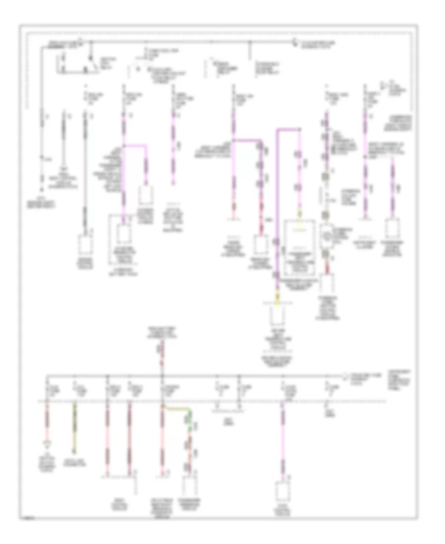
Power Distribution Wiring Diagram (1 of 6) for Chevrolet Impala LTZ 2014
 https://portal-diagnostov.com/license.html
Automotive Electricians Portal FZCO
Automotive Electricians Portal FZCO
https://portal-diagnostov.com/license.html
https://portal-diagnostov.com/license.html
Automotive Electricians Portal FZCO
Automotive Electricians Portal FZCO
List of elements for Power Distribution Wiring Diagram (1 of 6) for Chevrolet Impala LTZ 2014:
- (body harness, 5 cm forward of breakout, of branch to x500) (w/ gare door opener) j228
- Abs pump fuse 60a
- Abs valve fuse 30a
- Amp fuse 25a
- Audio amplifier
- Batt rvc fuse 5a
- Battery
- Battery fuse block
- Bcm 6 fuse 15a
- Body control module
- Brake booster pump motor relay (2.4l & 3.6l)
- Brk vac pump fuse 20a
- Ccm fuse 20a
- Chassis control module
- Driver window switch
- Ecm batt fuse 5a
- Electronic brake control module
- Engine control module
- Epb fuse 30a
- Front seat heating control module (if equipped)
- Fuse 100a
- Fuse 250a
- Fuse 300a
- Fuse 30a
- Fuse 60a
- Fuse 80a
- Garage door opener (if equipped)
- Generator
- Htd seat lf fuse 15a
- Htd seat rf fuse 15a
- Keyless entry control module (if equipped)
- Left rear window switch
- Mem seat fuse 5a
- Mir ewl fuse 7.5a
- Mirror control module
- Outside rearview mirror switch
- Parking brake control module
- Passenger window switch
- Peps batt fuse 5a
- Power steering control module (w/ belt drive)
- Power steering control module (w/o belt drive)
- Pwin frt fuse 30a
- Pwin rr fuse 30a
- Rap fuse 30a
- Red
- Right rear window switch
- Seat memory control module
- Starter motor
- Sunroof fuse 30a
- Sunroof motor (if equipped)
- Sunroof sunshade motor module (if equipped)
- To ignition main relay (diagram 2 of 6)
- To instrument panel fuse block (diagram 2 of 6)
- To instrument panel fuse block (diagram 4 of 6)
- Underhood fuse block (right side of engine compt)
- W/ memory
- W/o memory
- X210
- X310
- X320
- X390
- X400
- X500
- X505
- X600
- X605
- X700
- X800
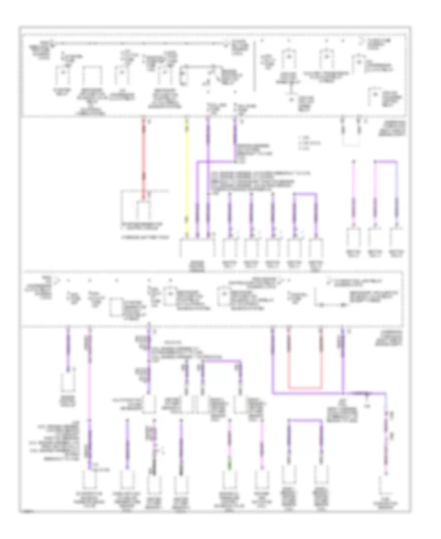
Power Distribution Wiring Diagram (2 of 6) for Chevrolet Impala LTZ 2014
List of elements for Power Distribution Wiring Diagram (2 of 6) for Chevrolet Impala LTZ 2014:
- (body harness, 25 cm rearward of breakout to x700) j339
- (not used)
- 7.5a
- Active grille air shutter actuator (if equipped)
- Aero shutter fuse 5a
- Air bag fuse 10a
- Auxiliary heater coolant pump relay (hybrid)
- Bcm 2 fuse 15a
- Bcm 3 fuse 15a
- Body control module
- Body ign fuse 10a
- Body ign2 fuse 15a
- Bpim ign fuse 5a
- C12
- Cabin cool pmp fuse 5a
- Chassis control module (hybrid)
- Data link connector
- Disply ign fuse 5a
- Dlc fuse 7.5a
- Dlis fuse 2a
- Driver cushion seat blower assembly
- Driver seat temperature control module
- Ecm ign fuse 5a
- Engine control module
- From battery fuse block (diagram 1 of 6)
- From body control module (diagram 6 of 6)
- From ccm fuse d (diagram 1 of 6)
- Fuse a
- G101 (engine compt center front)
- Hvac control module
- Hvac/ cntrl fuse 10a
- Hybrid/ev battery pack
- Ignition main relay
- Inflatable restraint sensing & diagnostic module
- Inside rearview mirror (if equipped)
- Instrument cluster
- Instrument panel fuse block (right kick panel)
- J100
- J331 (body harness, 6 cm forward x210 of breakout to x310)
- J336 (body harness, 5 cm rearward of breakout to x700)
- J994
- Passenger air bag disable indicator
- Passenger cushion seat blower assembly
- Passenger presence module
- Passenger seat temperature control module
- Pnk
- Rear defogger relay
- Rearview camera (if equipped)
- Red
- Starter/ generator control module
- Steering column fuse holder
- Steering wheel air bag coil
- Steering wheel heating control module (if equipped)
- To ignition switch (diagram 6 of 6)
- To ip ign (diagram 5 of 6)
- To starter fuse (diagram 3 of 6)
- Trunk rel fuse (diagram 4 of 6)
- Underhood fuse block (right side of engine compt)
- Windshield washer pump relay
- X105
- X210
- X310
- X320
- X400
- X900
- X915
Power Distribution Wiring Diagram (3 of 6) for Chevrolet Impala LTZ 2014
List of elements for Power Distribution Wiring Diagram (3 of 6) for Chevrolet Impala LTZ 2014:
- (3.6l: engine harness, 5.9 cm from breakout to x115) (2.4l: engine harness, 6.1 cm from breakout to crankshaft position sensor) (2.4l: engine harness, 16.9 cm from branch to rear of engine components) j106
- (3.6l: engine harness, 9.1 cm from breakout to x160) (2.5l: engine harness, 7 cm from g122) j107
- (engine harness, 35.3 cm from breakout to x160) (3.6l) j133
- 2.4l
- 2.5l
- 2.5l & 3.6l
- 3.6l
- 3.6l & 2.4l
- 3.6l & 2.5l
- A/c clutch fuse 10a
- A/c compressor clutch relay
- Auxiliary transmission fluid pump relay (hybrid)
- Bank 1 sensor 1 heated oxygen sensor (3.6l)
- Bank 1 sensor 2 heated oxygen sensor (3.6l)
- Bank 2 sensor 1 heated oxygen sensor (3.6l)
- Bank 2 sensor 2 heated oxygen sensor (3.6l)
- Bas pwr inverter fuse 175a
- Coil even fuse 15a
- Coil odd fuse 15a
- Cooling fan high speed relay
- Cooling fan low speed relay
- Cooling fan speed control relay
- Ecm fuse 25a
- Engine control module
- Engine controls ignition relay
- Engine oil pressure control solenoid valve (2.5l)
- Evaporative emission purge solenoid valve
- Fan rly a fuse 10a
- From a/c l compressor clutch relay (diagram 3 of 6)
- From e cabin cool pmp fuse (diagram 2 of 6)
- From engine controls ignition relay (diagram 3 of 6)
- Fuel composition sensor
- Heated oxygen sensor 1
- Heated oxygen sensor 2 (2.4l)
- Heated oxygen sensor 2 (2.5l)
- Hybrid/ev battery pack
- Ignition coil 1
- Ignition coil 2
- Ignition coil 3
- Ignition coil 4
- Ignition coil 5 (3.6l)
- Ignition coil 6
- J108 (2.5l: engine harness, 4 cm from branch to camshaft position sensors) (2.4l: engine harness, 4 cm from ignition coil 3) (3.6l: engine harness, 27.3 cm from breakout to x160)
- J227 (3.6l) (body harness, 15.9 cm forward of breakout, of branch to x500)
- Mass air flow/ intake air temperature sensor (2.4l)
- Multi-function intake air sensor
- Nca
- Non walk pt fuse 10a
- Non wlk pt fuse 10a
- Red
- Rocker arm actuator (2.5l)
- Sair pump fuse 50a
- Sair sol fuse 15a
- Secondary air injection pump relay (w/ california emission system)
- Secondary air injection solenoid valve relay (except hybrid)
- Secondary air injection solenoid valve relay (w/ california emission system)
- Secondary air injection solenoid valve relay (w/ california hybrid system)
- Starter fuse 30a
- Starter relay
- Starter/ generator coolant pump relay (hybrid)
- Starter/generator control module
- To ecm fuse (diagram 3 of 6)
- To front fog lamp relay (diagram 5 of 6)
- To sair sol fuse (diagram 3 of 6)
- Underhood fuse block (right side of engine compt)
- X10
- X150
- X190
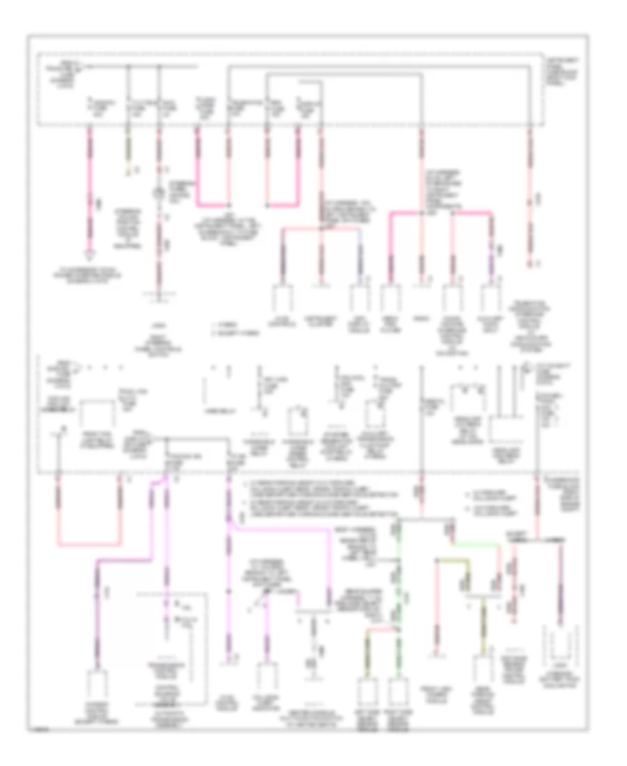
Power Distribution Wiring Diagram (4 of 6) for Chevrolet Impala LTZ 2014
List of elements for Power Distribution Wiring Diagram (4 of 6) for Chevrolet Impala LTZ 2014:
- (diagram 2 of 6)
- (or red)
- (w/o ventilated seats: passenger seat x210 cushion harness, in the passenger seat cushion) (w/ ventilated seats: seat temperature x320 control module- passenger, in the passenger seat cushion vent mat) j322
- 110v ac phase a
- 110v ac phase b
- 220v ac phase a
- 220v ac phase b
- Accessory dc/ac power inverter module
- Accessory power receptacle 220v ac (220v ac) accessory power receptacle 110v ac (110v ac)
- Bcm 1 fuse 15a
- Bcm 4 fuse 15a
- Bcm 5 fuse 15a
- Bcm 7 fuse 15a
- Bcm 8 fuse 30a
- Blower motor
- Body control module
- Center console accessory power receptacle
- Center console compartment accessory power receptacle
- Driver seat adjuster switch
- Drvr/seat circuit breaker 25a
- From battery fuse block (diagram 1 of 6)
- From fuse 19 h
- From instrument panel fuse block (diagram 5 of 6)
- From underhood fuse block (diagram 1 of 6)
- Frt/ hvac fuse 40a
- G305 (left front "a" pillar)
- G307 (below driver seat)
- Gnd dc to ac inverter ctrl
- Instrument panel accessory power receptacle
- Instrument panel fuse block (right kick panel)
- J204
- J208
- J301
- Logic
- Nca
- Pass/seat circuit breaker 25a
- Passenger seat adjuster switch
- Passenger seat lumber support switch
- Pwr/ outlet1 fuse 20a
- Pwr/outlet2 fuse 20a
- Rear compartment lid unlatch relay
- Red
- Retained accessory power relay
- Seat memory control module
- To acdcinv (diagram 5 of 6)
- Transmission shift lever position indicator
- Trunk rel fuse 5a
- W/ 2 way power seat
- W/ 8 way power seat
- W/ memory
- W/o memory
- X210
- X300
- X310
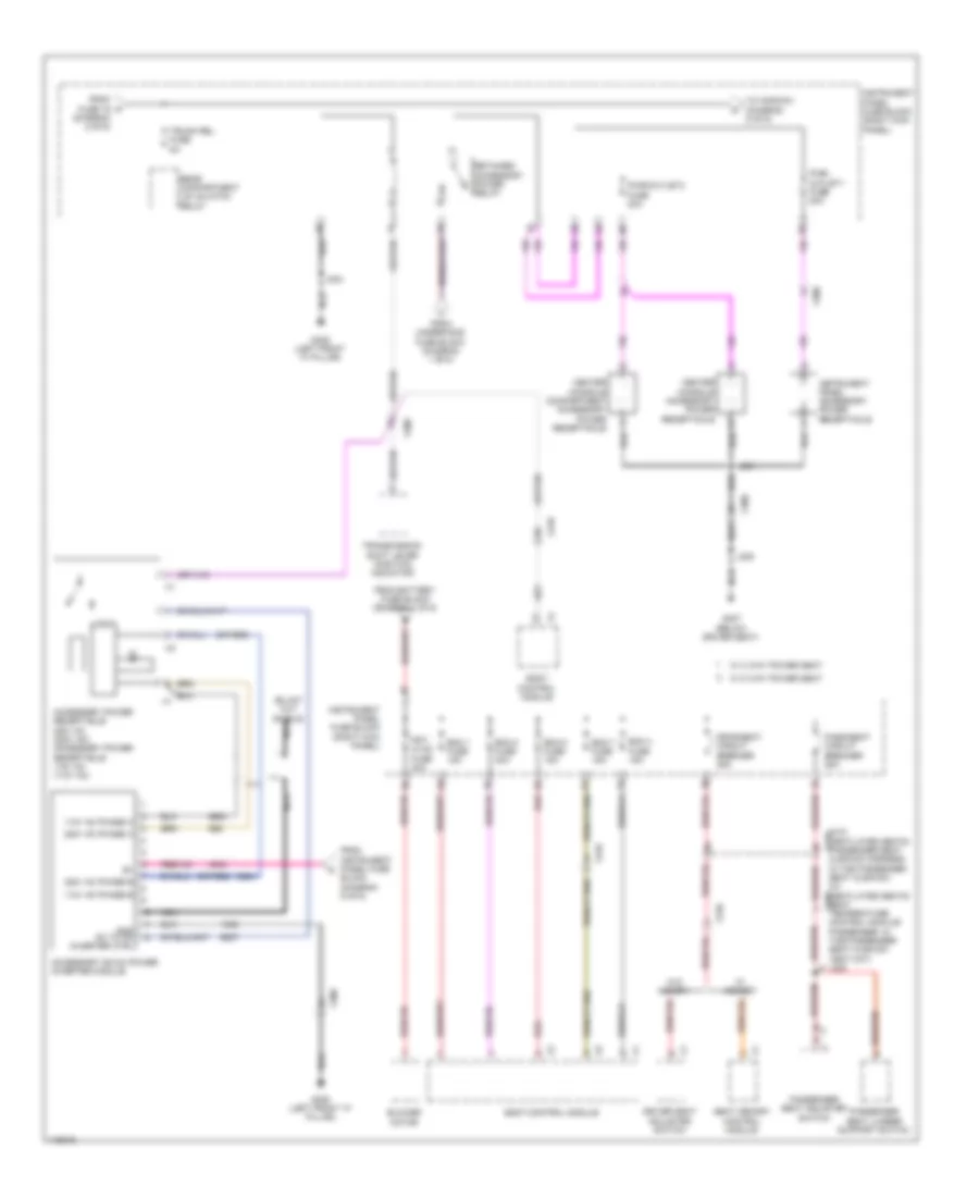
Power Distribution Wiring Diagram (5 of 6) for Chevrolet Impala LTZ 2014
List of elements for Power Distribution Wiring Diagram (5 of 6) for Chevrolet Impala LTZ 2014:
- (body harness, 13.2 cm rearward of branch to left rear wheel well) j401
- (i/p harness, 10.1 cm from branch to left instrument panel switches) j210
- (i/p harness, 9.5 cm left of branches to right instrument panel components)
- (rear bumper harness, 71 cm from side object sensor module - right) j417
- (w/ vehicle gps communication system)
- 2.4l & 2.5l
- 3.6l
- Acdcinv fuse 30a
- Automatic transmission assembly
- Auxiliary audio input
- Auxiliary transmission fluid pump relay (hybrid)
- Center console multi-function switch (w/ heated seats)
- Chassis control module (except hybrid)
- Collision alert
- Collision alert indicator
- Collision alert,rear cross traffic alert, lane departure warning & side obstacle detection
- Control solenoid valve assembly
- Cool fan lo k1 fuse 40a
- Cooling fan low speed relay
- Display fuse 15a
- Distance sensing cruise control module
- Except hybrid
- From display f ign fuse (diagram 2 of 6)
- From sair sol m fuse (diagram 3 of 6)
- From trunk rel n fuse (diagram 4 of 6)
- Front fog lamp relay (if equipped)
- Front view camera module
- Frt wpr fuse 30a
- Headlamp high beam relay
- Headlamp low beam relay (w/ hid headlamps)
- Horn relay
- Human machine interface control module (w/ navigation)
- Hvac control module
- Hvac controls
- Hybrid
- Hybrid/ev battery pack cooling fan
- Info display module
- Instrument cluster
- Instrument panel fuse block (right kick panel)
- Ip ign fuse 5a
- J200
- J201 (i/p harness, in the instrument panel, left, on breakout to fuse block - instrument panel)
- Left side object sensor module
- Logic
- Logic/ mode fuse 30a
- Media disc player
- Mgu cool pmp fuse 10a
- Obstcl fuse 10a
- Power pack acc fuse 10a 15a
- Radio
- Rdo fuse 15a
- Rear parking assist control module
- Right side object sensor module
- Right steering wheel controls switch
- Starter/ generator coolant pump relay (hybrid)
- Steering column position control module (if equipped)
- Steering wheel air bag coil
- Swc fuse 2a
- Tcm/ccm ign fuse 7.5a
- Telematics communication interface control module
- Telematics fuse 10a
- Tilt/tele fuse 15a
- To accessory dc/ac power inverter module (diagram 4 of 6)
- To tcm batt fuse (diagram 6 of 6)
- Trans aux pmp fuse 30a
- Transmission control module
- Underhood fuse block (right side of engine compt)
- W/ forward
- W/ rear parking assist & w/ forward
- W/ rear parking assist & w/o forward collision alert,rear cross traffic alert, lane departure warning & side obstacle detection
- W/o forward collision alert
- Windshield wiper relay
- Windshield wiper speed control relay
- X115
- X150
- X202
- X210
- X300
- X415
Power Distribution Wiring Diagram (6 of 6) for Chevrolet Impala LTZ 2014
List of elements for Power Distribution Wiring Diagram (6 of 6) for Chevrolet Impala LTZ 2014:
- (base of left "a" pillar) g203
- (body harness, 18.6 cm from breakouts to starter/generator control module) j400
- (except hybrid)
- (hybrid)
- 2.4l & 2.5l
- 3.6l
- Acc
- Acc led
- Acc volt
- Acc volt run/crank ign 1 volt x3
- Automatic transmission assembly
- Body control module
- Bpim batt fuse 7.5a 10a
- Cann vent fuse 5a
- Control solenoid valve assembly
- Cool fan hi k2 fuse 40a
- Cooling fan high speed relay
- Evaporative emission vent solenoid valve
- Except hybrid
- From headlamp p high beam relay (diagram 5 of 6)
- From instrument panel fuse block (diagram 2 of 6)
- Hybrid
- Hybrid/ev battery pack
- Ign
- Ignition mode switch (w/ keyless engine start switch)
- Ignition switch (w/o keyless engine start switch)
- Interior lights system
- Key in ignition switch
- Keyless entry control module
- Led sig
- Low ref
- Mode ctrl
- Mode volt
- Off
- Run
- Run/crank ign 1 volt x2
- Run/crank rly coil ctrl x4
- Start
- Starter/generator control module
- Tcm batt fuse 15a
- To underhood fuse block (diagram 2 of 6)
- Transmission control module
- Underhood fuse block (right side of engine compt)
- W/ keyless engine start switch
- W/o keyless engine start switch
- X210
- X350

 Čeština
 Dansk
Dansk Deutsch
 Ελληνικά
 English
 English
 Español
 Suomi
Suomi Français
 Français
 עברית
עברית Hrvatski
 Magyar
 Italiano
 日本語
日本語 한국어
한국어 Nederlands
 Polski
 Português
 Română
 Русский
 Slovenčina
 Slovenščina
 Svenska
 Türkçe
 中文 (中国)