POWER DISTRIBUTION
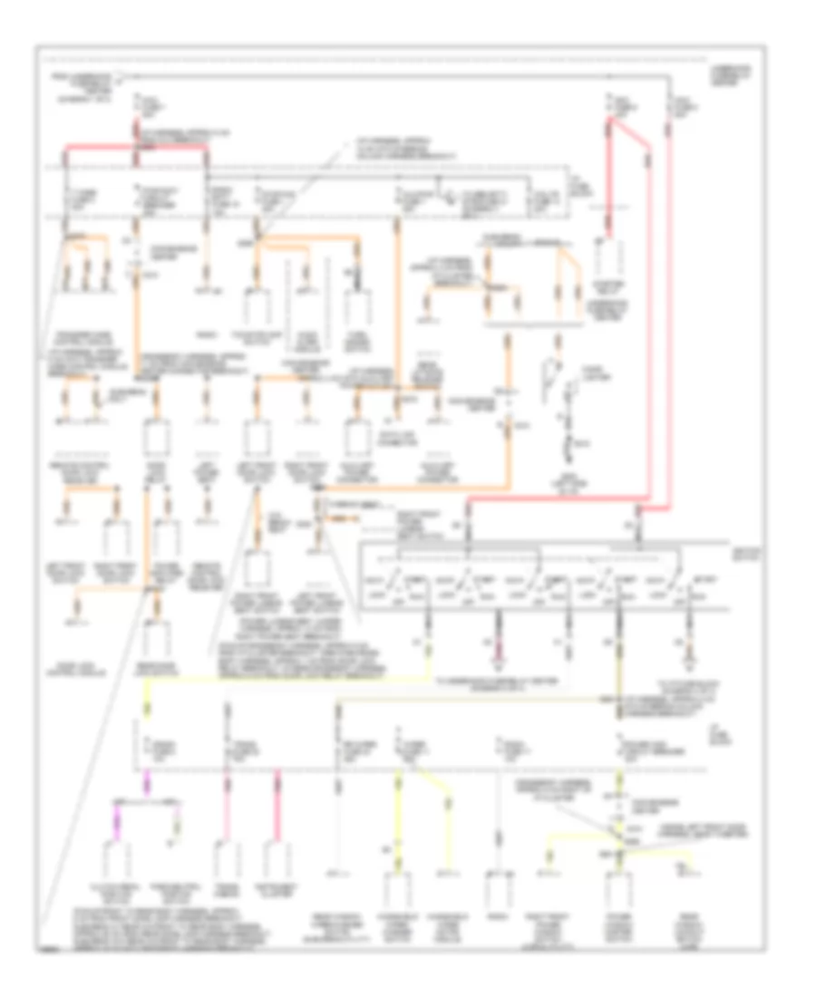
Power Distribution Wiring Diagram (1 of 4) for Chevrolet Pickup K2500 1997


List of elements for Power Distribution Wiring Diagram (1 of 4) for Chevrolet Pickup K2500 1997:
- (diesel)
- (diesel-engine harness, approx 5 cm from break- out to glow plug relay, gasoline-engine harness, approx 11 cm into under- hood fuse-relay center breakout)
- (engine harness, 4-13 cm from fuse-relay center breakout)
- (engine harness, approx 18 cm into underhood fuse-relay center break- out) s113
- (except diesel)
- (gasoline)
- (i/p harness, approx 5 cm from dlc harness breakout) s205
- (rear heat and a/c harness, 11-23 cm from blower motor relays breakout) s401
- (stud a)
- (stud b)
- (vanity mirror jumper harness, approx 4 cm from inside rearview mirror)
- A/c comp mini fuse 20a
- A/c maxi fuse 3 50a
- A/c relay
- Aux fan relay mini fuse 20a
- Auxiliary cooling fan relay
- Blower relay
- Brake lamp relay
- C13
- C205
- C219
- Cargo lamp switch (pick-up only)
- Convenience center
- Ctsy fuse 3 20a
- D13
- Daytime running lamps relay
- Diesel
- Diode
- Drl/fog fuse 15 20a
- Ecm-b mini fuse 20a
- Electronic brake control module
- Fog lamp relay
- Front dome reading lamps
- Fuel pump oil pressure switch and sender
- Fuel pump relay
- Fusible link (10 ga-rust)
- Gas
- Generator
- Headlamp and panel dimmer switch
- Heater and a/c control switch
- High blower relay
- Horn mini fuse 20a
- Horn relay
- I/p compartment lamp
- I/p fuse block
- Interior lamp control module
- Left battery (diesel)
- Left courtesy lamp
- Left front door courtesy lamp
- Left illuminated vanity mirror
- Left rear door courtesy lamp
- Low blower relay
- Maxi fuse 2 30a
- Maxi fuse 30a
- Maxi fuse 4 60a
- Maxi fuse 8 50a
- Medium blower relay
- Pk lps fuse 9 20a
- Powertrain control module (diesel)
- Rear dome reading lamps
- Red
- Remote battery stud
- Remote outside rearview mirror switch
- Right battery
- Right courtesy lamp
- Right front door courtesy lamp
- Right illuminated vanity mirror
- Right rear door courtesy lamp
- Rr defog mini fuse 20a
- S101
- S110 red
- S242 (i/p harness, approx 12 cm from radio harness breakout)
- S248 (crossbody harness, approx 35 cm from rear speaker breakout)
- S312
- Spare power source
- Starter motor solenoid
- To fusible link (diagram 4 of 4)
- To underhood fuse-relay center (diagram 2 of 4)
- Underhood fuse- relay center
- Underhood fuse-relay center
- Underhood lamp
- Underhood reel lamp
- Vehicle control module (gasoline)
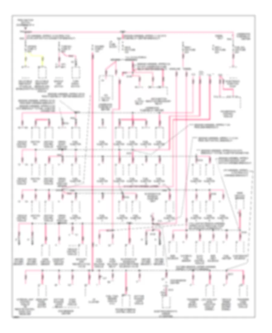
Power Distribution Wiring Diagram (2 of 4) for Chevrolet Pickup K2500 1997
List of elements for Power Distribution Wiring Diagram (2 of 4) for Chevrolet Pickup K2500 1997:
- (crossbody harness, approx 11 cm from convenience center connector breakout) s255
- (crossbody harness, approx 8 cm right of i/p cluster
- (i/p harness, approx 12 cm into steering column harness breakout)
- (i/p harness, approx 4 cm from i/p cluster breakout)
- (i/p harness, approx 4 cm into auxiliary power outlet)
- (i/p harness, approx 4 cm into transfer case control module breakout)
- (i/p harness, approx 8 cm from dlc breakout) s200
- (inside left front door harness, near tweeter)
- (pickup-crossbody harness, approx 9 cm from i/p cluster breakout, crewcab-cross- body harness, approx 1 cm from door lock relay breakout, others-crossbody harness, approx 6 cm from door lock relay breakout)
- (pickup-front to rear body harness, approx 6 cm from front dome lamp harness breakout, suburban w/ rear a/c-front to rear body harness, approx 55 cm from rear dome lamp harness breakout, suburban w/o rear a/c-front to rear body harness, approx 25 cm into crossbody harness breakout)
- (power lumbar seat jumper harness, approx 13 cm from right power seat breakout)
- A/t
- Acc
- Audio alarm module
- Aux/pwr fuse 7 25a
- Auxiliary power connector
- C210
- Cig ltr fuse 13 20a
- Cigar lighter
- Clutch pedal position switch
- Convenience center
- Crank fuse 8 10a
- D14
- D15
- Data link connector
- Door lock control module
- Door lock relay
- From underhood a fuse-relay center (diagram 1 of 4)
- G202 (left side of i/p)
- Harness breakout)
- I/p fuse block
- Ignition switch
- Instrument cluster
- Left front door lock switch
- Left front power lumbar seat switch
- Left power seat
- Lock
- M/t
- Maxi fuse 5 50a
- Maxi fuse 6 40a
- Maxi fuse 7 50a
- Nca
- Off
- Park/neutral position switch
- Pickup
- Pnk
- Power amplifier relay
- Power wdo circuit breaker 30a
- Power window master switch
- Pwr-accy circuit breaker 20a
- Radio
- Radio batt fuse 19 10a
- Radio fuse 17 10a
- Rear door lock switch
- Rear liftgate release switch
- Rear window lockout switch (4-dr)
- Rear window wiper/washer switch (suburban/utility)
- Red
- Remote control door lock receiver
- Right front door lock switch
- Right front power lumbar seat switch
- Right front power window switch (2 dr & utility)
- Rr wiper fuse 23 25a
- Run
- S201
- S218
- S256
- S264
- S266
- S270
- S299
- S300
- S434
- Start
- Starter relay
- Stop/haz fuse 1 20a
- Suburban only
- Suburban/ utility
- T case fuse 2 20a
- Tcc/stoplamp switch
- To i/p fuse block (diagram 4 of 4)
- To security/ strg fuse 21 (diagram 4 of 4)
- To underhood fuse-relay center (diagram 3 of 4)
- Trans fuse 20 10a
- Trans- mission
- Transfer case control module
- Turn/ hazard switch
- Underhood fuse-relay center
- W/bench seat
- W/o bench seat
- Windshield wiper motor module
- Windshield wiper/ washer switch
- Wiper fuse 11 25a
Power Distribution Wiring Diagram (3 of 4) for Chevrolet Pickup K2500 1997
List of elements for Power Distribution Wiring Diagram (3 of 4) for Chevrolet Pickup K2500 1997:
- (a/t)
- (engine harness, approx 11 cm into fuse-relay center breakout) pnk
- (engine harness, approx 11-13 cm from ignition coil breakout)
- (engine harness, approx 22 cm into underhood fuse- relay center breakout)
- (engine harness, approx 29 cm from fuse-relay center breakout)
- (engine harness, approx 30 cm from egr harness breakout)
- (engine harness, approx 5 cm from backup lamp switch harness breakout)
- (engine harness, approx 7 cm from egr breakout)
- (engine harness, approx 8 cm into breakout to fuel injector connector)
- (i/p harness, approx 10 cm from tcc/ stoplamp switch connector breakout) pnk
- (i/p harness, approx 13 cm from dlc harness breakout)
- (in injector harness jumper)
- (m/t)
- (oxygen sensor jumper harness, approx 17 cm into harness)
- (taillamp extension harness, approx 65 cm from fuel pump balance module breakout)
- 4.3l
- 5.0l, 5.7l
- 6.5l
- 7.4l
- 7.4l w/ california emissions
- A/c clutch relay
- Air bag fuse 10 10a
- Air injection reaction secondary relay
- Audio alarm module
- B pnk
- Backup lamp switch
- C pnk
- C11
- C12
- C218
- Camshaft position sensor
- Convenience center
- Crank- shaft position sensor
- Daytime running lamps module
- Daytime running lamps relay
- Diesel
- Diesel only
- Ecm 1 mini fuse 20a
- Egr solenoid
- Egr vent solenoid
- Electrochromatic mirror w/ compass
- Electronic injection pump
- Eng-1 mini fuse 20a
- Evaporative emission canister vent
- Evaporative emissions canister purge solenoid valve
- Exhaust gas recirculation valve
- From ignition switch (diagram 2 of 4)
- Fuel heater
- Fuel injector
- Fuel pump balance module
- Fuel pump balance relay
- Fuel sol mini fuse 20a
- Fuel tank sender module (4.3l)
- Gasoline
- Gauges fuse 4 10a
- Glow plug control module
- Headlamp/ panel dimmer switch
- Heated oxygen sensor 1
- Heated oxygen sensor 2
- Heated oxygen sensor 3
- Heated oxygen sensor 4
- I/p cluster
- I/p fuse block
- Ign e mini fuse 10a
- Ignition coil
- Ignition control module
- Inflatable restraint i/p module enable switch
- Inflatable restraint sensing and diagnostic module
- Interior lamp control module or remote control door lock receiver
- Low coolant level indicator module (diesel)
- M/t
- Mass air flow sensor
- Mass airflow sensor
- Nca
- Nca
- Others
- Pnk
- Pnk s104
- Pnk s154
- Pnk s207
- Power steering control module
- Powertrain control module
- S104
- S108
- S109
- S146
- S148
- S155 pnk
- S161
- S213 pnk
- S315
- Transfer case control module
- Transfer case select switch
- Turn b/u fuse 16 20a
- Turn signal switch
- Underhood fuse-relay center
- Vehicle control module
- Vehicle speed sensor buffer (diesel)
- Wastegate solenoid
- Water-in- fuel sensor
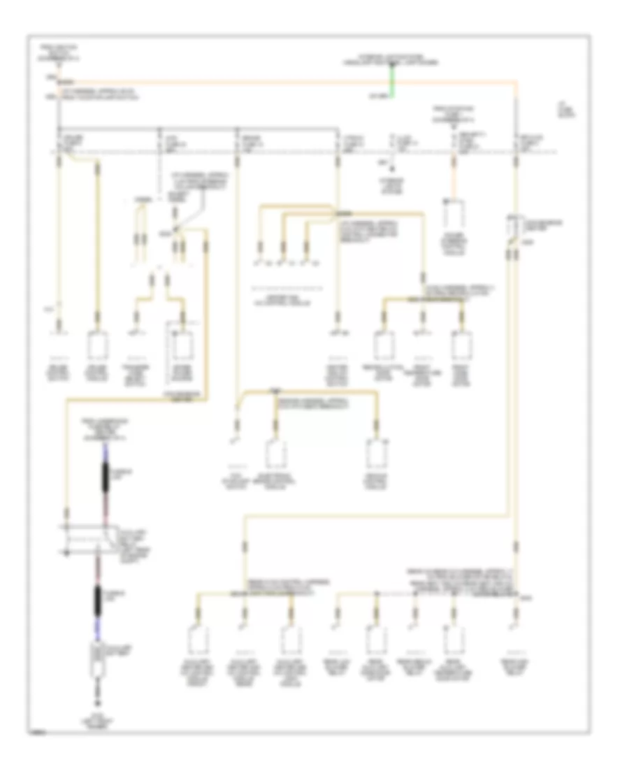
Power Distribution Wiring Diagram (4 of 4) for Chevrolet Pickup K2500 1997
List of elements for Power Distribution Wiring Diagram (4 of 4) for Chevrolet Pickup K2500 1997:
- (engine harness, approx 6 cm into ebcm breakout)
- (hvac harness, approx 4 cm from recirculation door breakout) s243
- (i/p harness, approx 29 cm from tcc/stoplamp switch)
- (i/p harness, approx 4 cm from steering column breakout)
- (i/p harness, approx 6 cm into heater a/c control connector breakout)
- (rear a/c-rear a/c harness, approx 17 cm from blower motor relays, rear heat and a/c-rear heat and a/c harness, approx 4 cm from blower motor relays)
- (rear hvac control harness, approx 5 cm from hvac logic module breakout) s308
- 4wd fuse 24 25a
- A13
- Auxiliary battery
- Auxiliary battery relay (left rear of engine compt)
- Auxiliary heater and a/c control logic module
- Auxiliary heater and a/c control module (front)
- Auxiliary heater and a/c control module (rear)
- Brake fuse 18 10a
- C205
- Convenience center
- Cruise control module
- Cruise control switch
- Cruise fuse 6 10a
- Diesel
- Electronic brake control module
- Except diesel
- From ignition switch (diagram 2 of 4)
- From stop/haz fuse 1 (diagram 2 of 4)
- From underhood fuse-relay center (diagram 1 of 4)
- Front mode door motor
- Front temperature door motor
- Fusible link
- G100 (left front fender)
- Heater and a/c control module
- Heater and a/c control switch
- Htr-a/c fuse 12 25a
- I/p fuse block
- Illum fuse 14 10a
- Interior lights system
- Interior lights system (headlamp and panel lamp dimmer)
- Power steering control module
- Rear auxiliary mode door motor
- Rear auxiliary temperature door motor
- Rear high blower relay
- Rear low blower relay
- Rear medium blower relay
- Recirculation door motor
- Rr hvac fuse 5 20a
- S151
- S206
- S235
- S268
- S400
- Security/ strg fuse 21 10a
- Spare power source
- Tcc/ stoplamp switch
- Transfer case select switch
- Vehicle control module

 Čeština
 Dansk
Dansk Deutsch
 Ελληνικά
 English
 English
 Español
 Suomi
Suomi Français
 Français
 עברית
עברית Hrvatski
 Magyar
 Italiano
 日本語
日本語 한국어
한국어 Nederlands
 Polski
 Português
 Română
 Русский
 Slovenčina
 Slovenščina
 Svenska
 Türkçe
 中文 (中国)