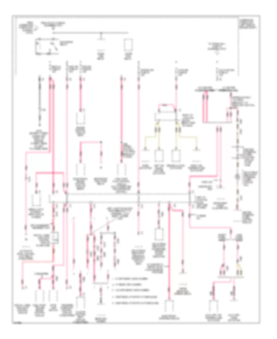
POWER DISTRIBUTION
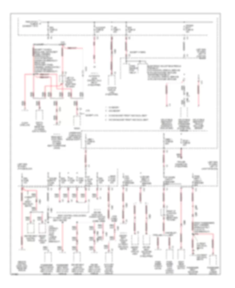
Power Distribution Wiring Diagram (1 of 8) for Chevrolet Suburban C1500 2012


List of elements for Power Distribution Wiring Diagram (1 of 8) for Chevrolet Suburban C1500 2012:
- (chassis harness, approx- imately 33 cm from breakout to g300) j366
- (fuse block jumper harness) j210
- (fuse block jumper harness) j211
- (if equipped)
- (not used)
- 125a
- 175a
- 2b1
- 60a
- Abs 2 fuse 9 25a
- Abs-1 fuse 61 40a
- Amp fuse 41 30a
- Assist step control module (w/ side retractable power running board steps)
- Audio amplifier
- Automatic level control (alc) compressor (if equipped)
- Automatic level control (alc) solenoid valve
- Automatic transmission
- Battery
- Blower motor control module
- Body control module (bcm)
- Brakes & except hybrid
- Cadillac escalade platinum appearance package
- Cadillac w/o one piece liftgate w/ lift glass
- Cargo bed lamp
- Control solenoid valve assembly
- Ecm-batt fuse 12 10a
- Elec run board fuse 65 30a
- Electronic brake control module (ebcm)
- Electronic suspension control (esc) module (w/ bi-state real time damping chassis package)
- Engine control module (ecm)
- Esc/alc exh fuse 2 30a
- Evaporative emission (evap) canister vent solenoid valve
- Except hybrid hybrid
- Exp/pto fuse 47 15a
- Fscm fuse 21 20a
- Fuel pump flow control module
- Fuel pump/ trailer brake control module (10 series)
- Fuse b 30a
- Fuse d 30a
- Fuse holder (on positive battery post)
- Generator
- Generator inline fuse
- Heated & cooled cup holder
- Heavy duty abs fuse 59 60a
- Hvac batt fuse 39 10a
- Hvac blwr fuse 70 40a
- Hvac control module
- Hybrid
- Instrument panel cluster (ipc)
- Ipc fuse 46 10a
- Itbc fuse 6 15a
- J450
- Jumper harness) j209
- Left & right pillar mounted halogen spot lamp
- Left i/p junction block (left end of dash)
- Left spot lamp
- Mobile radio fuse block
- Nca
- Power brakes except hybrid
- Power tonneau cover exit/ learn switch
- Power tonneau cover master motor
- Power tonneau cover receiver module
- Power tonneau cover slave motor
- Red
- Red/
- Relay a
- Relay b
- Right i/p junction block (right end of dash)
- Right i/p junction block (right end of x6 dash)
- Roof beacon relay (if equipped)
- S/roof fuse 34 30a
- Starter
- Stud 2 fuse 63 30a
- Sunroof control module (w/ sun glass sliding electric roof)
- Tcm-batt fuse 14 15a
- To auxiliary fuse block (diagram 7 of 8)
- To dlis fuse 35 (diagram 5 of 8)
- To pwr/trn relay (diagram 4 of 8)
- To rdo fuse 42 (diagram 2 of 8)
- To run/crank relay (diagram 6 of 8)
- To seo b1 fuse 52 (diagram 3 of 8)
- To splice s271 (diagram 5 of 8)
- Trailer brake control module (20 series)
- Trailer brake control relay
- Transfer case encoder motor
- Transfer case shift control module
- Trec fuse 67 30a
- Underhood fuse block (left side of engine compt)
- W/ electric sunroof
- W/ hydraulic
- W/ hydraulic power brake
- W/ integrated trailer brake control
- W/ luxury
- W/ premium audio
- W/ vaccum
- W/ vaccum power brake control
- W/o electric sunroof
- W/o integrated trailer brake control
- W/o luxury
- Wsw/htr fuse 66 60a
- X109
- X116
- X117
- X129
- X210
- X211
- X214
- X313
- X400
- X450
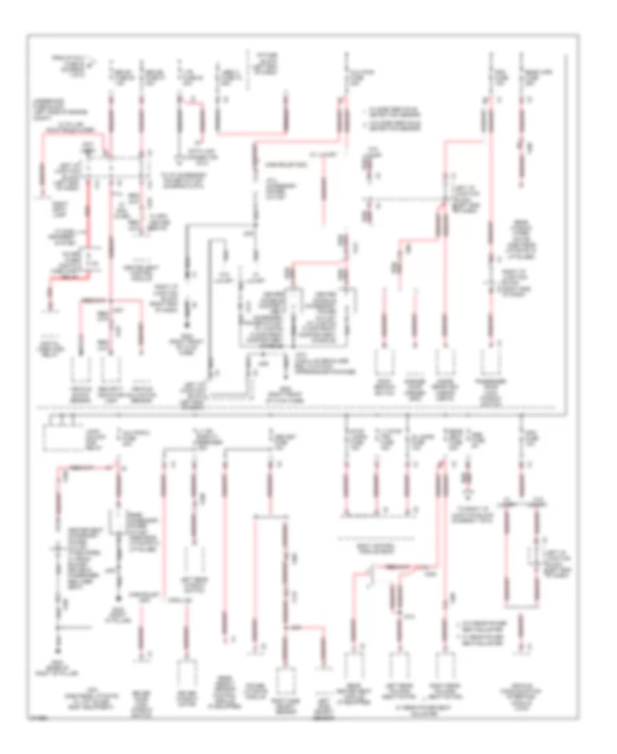
Power Distribution Wiring Diagram (2 of 8) for Chevrolet Suburban C1500 2012
List of elements for Power Distribution Wiring Diagram (2 of 8) for Chevrolet Suburban C1500 2012:
- (left end of dash) i/p fuse block
- (left end of dash) left i/p junction block
- 3b4
- Air bag batt fuse 45 15a
- Alc/comp fuse 58 40a
- Automatic level control (alc) relay (if equipped)
- Aux wdo circuit breaker 25a
- Auxiliary blower motor control module
- Bcm fuse 10a
- Body control module (bcm)
- Cadillac
- Chevrolet/ gmc
- Clock (cadillac)
- Cooled seats fuse 30a
- Ctsy fuse 15a
- Ddm fuse 15a
- Digital radio receiver (w/ s-band digital radio)
- Dim fuse 10a
- Driver door lock window switch
- Driver seat 2 circuit breaker 25a
- Driver seat adjuster switch (if equipped)
- Driver seat back ventilation heat & cool module
- Driver seat cushion ventilation heat & cool module
- Dsm fuse 10a
- Eap fuse 38 15a
- Electronic adjustable pedals pcb relay (w/o municipal special service & police package vehicles) rap/spare pcb relay (w/ municipal special service & police package vehicles)
- Except hybrid
- Except uys
- From stud 2 a fuse 63 (diagram 1 of 8)
- Heated seat control module
- Hybrid w/ front individual seats
- Inflatable restraint passenger presence system (pps) module
- Inflatable restraint sensing & diagnostic module (sdm)
- Inflatable restraint vehicle rollover sensor
- J318 (approxi- mately 10 cm from lumbar motor breakout)
- Lbec 1 fuse 64 60a
- Left i/p junction block (left end x4
- Lgm fuse 71 30a
- Liftgate module (lgm) (if equipped)
- Long wheel base
- Mbec 1 fuse 69 60a
- Memory seat module (msm)
- Memory seat module (msm) (w/ front individual seats)
- Of dash)
- Park enable pcb relay
- Pass seat 1 circuit breaker 25a
- Pass- enger door lock/ window switch
- Pass- enger window motor
- Passenger seat adjuster switch
- Passenger seat back ventilation heat & cool module
- Passenger seat cushion ventilation heat & cool module
- Passenger seat lumbar switch
- Radio
- Rdo fuse 42 15a
- Rear hvac fuse 30a
- Rear seat audio (rsa) control (w/ rear seat & earphone jacks)
- Red
- Remote control door lock receiver (rcdlr)
- Right i/p junction block (right end x3 of dash)
- Right rear window switch
- Rt doors circuit breaker 25a
- Rt stop trn fuse 15a
- Short wheel base
- Stud 1 fuse 68 40a
- Trailer connector (if equipped)
- Underhood fuse block (left side of engine compt)
- Uys
- W/ front cooling seat heater
- W/ front individual seats
- W/ luxury
- W/ memory
- W/ non bucket front individual seat
- W/o front individual seats
- W/o luxury
- W/o memory
- W/o non bucket front individual seat
- X11
- X12
- X202
- X211
- X212
- X303
- X305
- X407
- X800
Power Distribution Wiring Diagram (3 of 8) for Chevrolet Suburban C1500 2012
List of elements for Power Distribution Wiring Diagram (3 of 8) for Chevrolet Suburban C1500 2012:
- (not used)
- 3b2
- Aux pwr 2 fuse 20a
- Aux pwr fuse 20a
- Body control module (bcm)
- Cadillac
- Center console accessory power outlet (w/ custom floor front compartment console)
- Center console compart- ment accessory power outlet (w/ custom floor front compartment console)
- Center seat accessory power outlet (if equipped, w/ front bucket driver & passenger recliner seat)
- Chevrolet/ gmc
- Chevrolet/gmc
- Data link connector (dlc)
- Detection sensor
- Digital video disc relay
- Driver door lock/ window switch
- Driver window motor
- From stud 2 fuse 63 b (diagram 1 of 8)
- G200 (right front of hvac case)
- G304 (base of right "b" pillar)
- G402 (right "d" pillar)
- Garage door opener (gdo)
- Heated seat control module
- I/p 2 accessory power outlet
- I/p fuse block (left end of dash)
- Info fuse 10a
- Inline fuse digital video disc relay
- Inside rearview mirror (isrvm)
- Is lamps fuse 10a
- J200
- J203
- J304 (one piece liftgate w/ lift glass body equipment)
- J312
- J334 (cadillac escalade esc, platinum appearance package)
- J344
- J400
- Lbec 2 fuse 72 60a
- Left i/p junction block (left end of dash)
- Left i/p junction block (left end x10
- Left i/p junction block (left end x4
- Left rear folding seat motor
- Left rear window switch
- Left side object sensor
- Lock/ unlock pcb relay
- Lt dr circuit breaker 25a
- Lt stop trn fuse 15a
- Ltr fuse 53 20a
- Nca
- Obs det fuse 10a
- Of dash)
- Passenger door lock/ window switch
- Pdm fuse 15a
- Power liftgate module
- Rear accessory power outlet (one piece liftgate w/ liftglass)
- Rear heated seat module (if equipped)
- Rear object sensor control module (if equipped)
- Rear seat fuse 20a
- Rear window wiper motor (one piece liftgate w/ liftglass)
- Rear wpr fuse 25a
- Red
- Right i/p junction block (right end of dash)
- Right i/p junction block (right end x3
- Right rear folding seat motor
- Right side object sensor
- Right spot lamp
- Roof beacon switch
- Rse fuse 5a
- Seatadjuster
- Security indicator lamp
- Seo b1 fuse 52 15a
- Seo b2 fuse 37 30a
- Stop lamps fuse 15a
- To i/p accessory power outlet (diagram 8 of 8)
- To right i/p junction block (diagram 7 of 8)
- Underhood fuse block (left side of engine compt)
- Vehicle communication interface module (vcim)
- Vehicle inclination sensor
- Vehicle shock sensor
- W/ duel headrest system
- W/ luxury
- W/ pillar mounted halogen
- W/ rear power seat adjuster
- W/ rear power seatadjuster
- W/ side obstacle
- W/ spo alarm
- W/o luxury
- W/o rear power
- W/o side obstacle detection sensor
- X115
- X14
- X202
- X211
- X227
- X304
- X307
- X308
- X320
- X331 w/ spo heated seats
- X405
- X700
Power Distribution Wiring Diagram (4 of 8) for Chevrolet Suburban C1500 2012
List of elements for Power Distribution Wiring Diagram (4 of 8) for Chevrolet Suburban C1500 2012:
- (ignition coil jumper harness, approximately 3 cm from ignition coil 4 breakout) j110
- (ignition coil jumper harness, approximately 3 cm pnk from ignition coil 5 breakout) j107
- 5.3l & 6.2l
- A/c cmprsr relay
- Auxiliary fuse block (hybrid) (left side of engine compartment)
- Bck/up lamp pcb relay
- Drl pcb relay
- Ecm/throt cont fuse 5 15a
- Eng fuse 4 15a
- Engine control module (ecm)
- Evaporative emission (evap) canister purge solenoid valve
- Except 6.0l (vin g)
- Except hybrid
- Fan cntrl relay
- Fan cntrl relay (except hybrid)
- Fan hi relay
- Fan hi relay (except hybrid)
- Fan lo relay
- Fan lo relay (except hybrid)
- Fan mid 1 relay
- Fan mid 2 relay
- Fan-1 fuse 57 40a
- Fan-2 fuse 60 40a
- Fog lamp relay
- From stud 2 fuse 63 (diagram 1 of 8)
- Frt wash pcb relay
- Frt wpr fuse 36 25a
- Fuel injector
- Fuel pump relay
- Hdlp lo/hid relay
- Heated oxygen sensor (ho2s) bank 1 sensor 1
- Heated oxygen sensor (ho2s) bank 1 sensor 2
- Heated oxygen sensor (ho2s) bank 2 sensor 1
- Heated oxygen sensor (ho2s) bank 2 sensor 2
- Hi beam pcb relay
- Horn pcb relay
- Hybrid
- Ignition coil
- Inj-a fuse 24 20a
- Inj-b fuse 13 20a
- Mass air flow (maf) sensor/ intake air temperature (iat) sensor
- Nca
- O2-a snsr fuse 18 10a
- O2-b snsr fuse 8 10a
- Park lamp relay
- Pnk
- Pnk d
- Pwr/trn relay
- Rear defog pcb relay
- Rear wash pcb relay
- Strtr relay
- Trlr stop lt pcb relay
- Trlr stop rt pcb relay
- Underhood fuse block (left side of engine compt)
- Valve lifter oil manifold (vlom) assembly
- Wiper 1 pcb relay
- Wiper 2 pcb relay
- X111
- X113
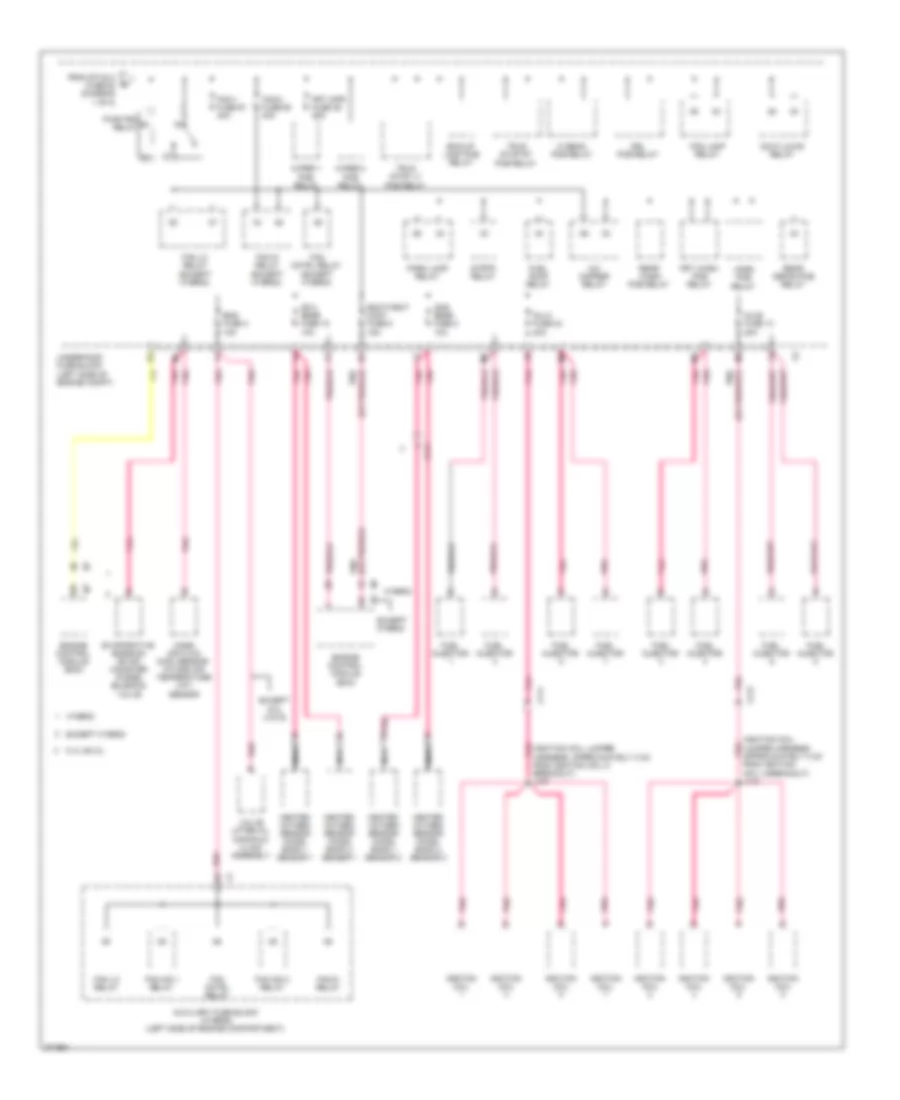
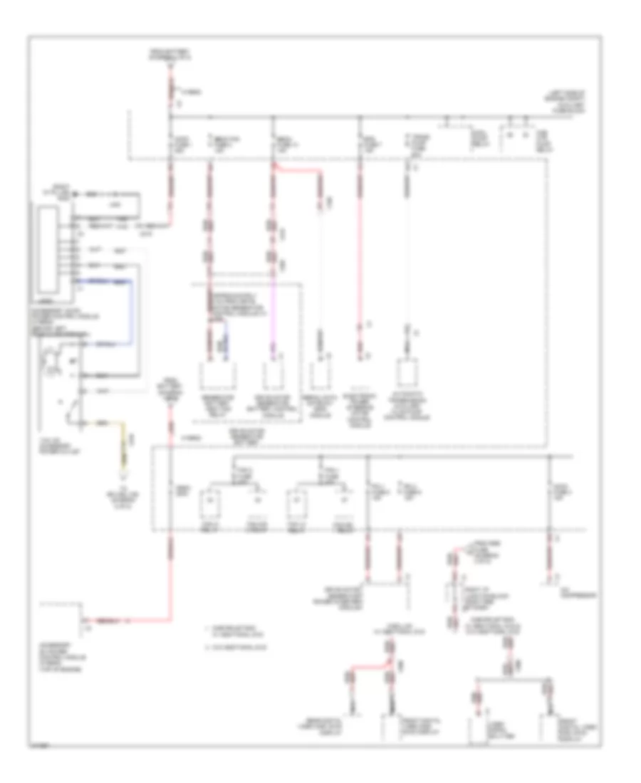
Power Distribution Wiring Diagram (5 of 8) for Chevrolet Suburban C1500 2012
List of elements for Power Distribution Wiring Diagram (5 of 8) for Chevrolet Suburban C1500 2012:
- (not used)
- 2b3
- 50a
- 5v ref
- A4 x201
- Acc
- Body control module (bcm)
- Digital video disc (dvd) relay
- Dlis fuse 35 2a
- From fuse holder (diagram 1 of 8)
- From stud 2 d fuse 63 (diagram 1 of 8)
- Ign volt
- Ignition switch
- J212 (steering column harness)
- J213 (steering column harness)
- J271 red
- Junction block
- Key-in switch
- Left i/p junction block (left end of dash)
- Mobile radio fuse block
- Nca
- Off
- Pnk
- Police provision 1 circuit breaker
- Police provision 2 circuit breaker
- Police provision 3 circuit breaker
- Rap/spare pcb relay (police package vehicle & municipal special service vehicle)
- Rear body upfitter 1
- Rear body upfitter 2
- Red
- Relay a
- Right i/p junction block (right end of dash)
- Run
- Start
- Sunroof module (if equipped)
- Theft deterrent module (tdm)
- To run/ crank relay (diagram 6 of 8)
- To splice j207 (diagram 8 of 8)
- To underhood fuse block (diagram 8 of 8)
- Transfer case shift control switch
- Turn/signal multi- function switch
- Underhood fuse block (left side of engine compt)
- W/ active two speed push button control transfer case
- W/ active two speed push button control transfer case, w/o rear window intermittent wiper system
- W/ dual dvd headrest system
- W/ rear window intermittent wiper system
- X114
- X14
- X201
- X219
- X221
- X222
- X223
- X313
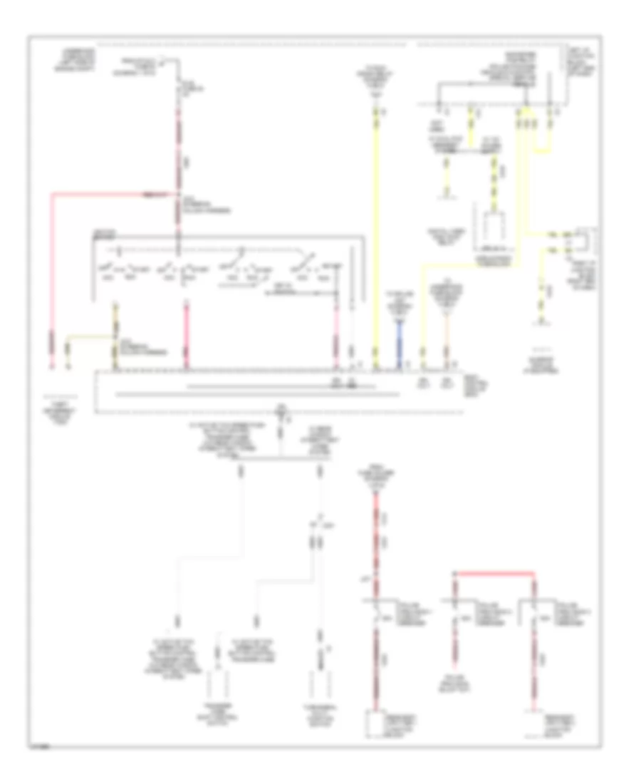
Power Distribution Wiring Diagram (6 of 8) for Chevrolet Suburban C1500 2012
List of elements for Power Distribution Wiring Diagram (6 of 8) for Chevrolet Suburban C1500 2012:
- (approximately 7 cm from breakout to headlight switch) j219
- 7.5a
- Air bag ign fuse 40 10a
- Automatic level control (alc) relay (if equipped)
- Aux hvac-ign fuse 48 10a
- Auxiliary air temperature actuator
- Auxiliary mode actuator
- Cadillac
- Chevrolet/ gmc
- Chmsl pcb relay
- Climate control seat module (if equipped)
- Digital video disc (dvd) control module
- Digital video disc (dvd) control module inline fuse
- Ecm-ign fuse 56 15a
- Electronic brake control module (ebcm)
- Electronic compass module
- Engine control module (ecm)
- From stud 2 fuse 63 (diagram 1 of 8)
- From underhood fuse block g (diagram 5 of 8)
- Fuel pump flow control module (w/o integrated trailer brake control)
- Fuel pump/ trailer brake control module
- G102 (except hybrid: lower left front of engine) (hybrid: rear of left cylinder head)
- Heated steering wheel control module
- Heated steering wheel control module inline fuse
- Hvac-ign fuse 55 10a
- If equipped
- Inflatable restraint passenger air bag on/off indicator
- Inflatable restraint sensing & diagnostic module (sdm)
- Inflatable restraint steering wheel module coil
- Inside rearview mirror (isrvm)
- Instrument panel cluster (ipc)
- J105
- J365 (appro- ximately 37 cm from breakout to g300) pnk
- L/gate pcb relay
- Left air tempe- rature actuator
- Left i/p junction block (left end of dash)
- Left junction block) from breakout to harness, 10 cm (body jumper j278
- Long wheel base
- Misc ign fuse 43 10a
- Mode actuator
- Nca
- One piece liftgate w/ fixed glass
- One piece liftgate w/o fixed glass
- Pnk
- Rearview camera
- Recirculation actuator
- Red
- Right air temperature actuator
- Right i/p junction block (right end of dash)
- Run/crank relay
- Secondary fuel pump relay
- Seo/alc fuse 54 10a
- Serial data gateway (sdg) module (hybrid)
- Short wheel base
- Spo accessory headrest dvd
- Stop lamp switch
- To trans ign 1 fuse 19 (diagram 8 of 8)
- Transfer case shift control module (if equipped)
- Underhood fuse block (left side of engine compt)
- W/ comfort & decor level 3 convenience package
- W/ heated steering wheel
- W/ rear a/c
- W/ rear view camera
- W/ spo rear vision camera
- W/o heated steering wheel
- W/o spo rear vision camera
- X11
- X115
- X12
- X14
- X201
- X205
- X217
- X276
- X277
- X278
- X304
- X305
- X310
- X407
- X409
- X413
- X452
- X902
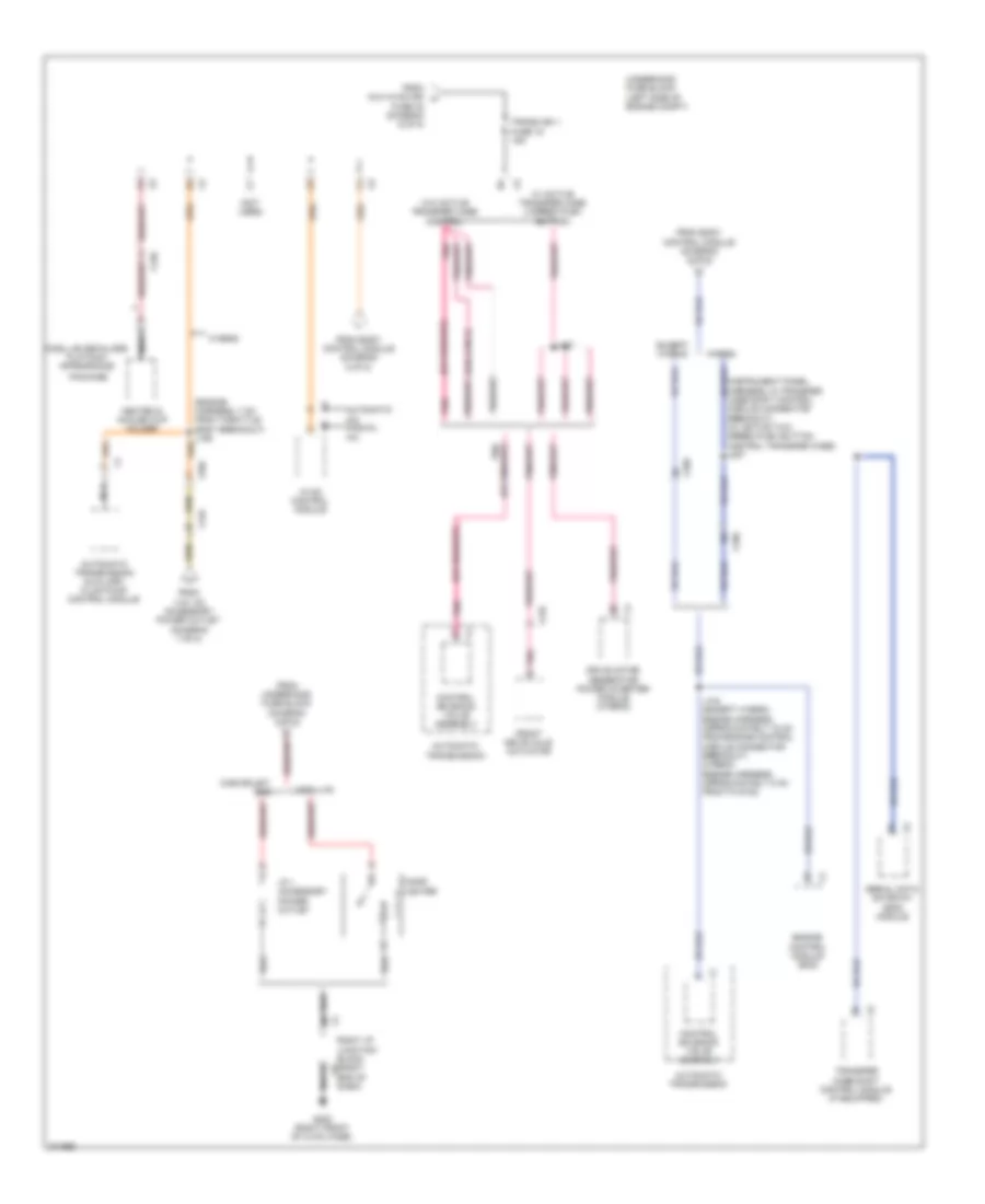
Power Distribution Wiring Diagram (7 of 8) for Chevrolet Suburban C1500 2012
List of elements for Power Distribution Wiring Diagram (7 of 8) for Chevrolet Suburban C1500 2012:
- (left side of engine compt) auxiliary fuse block
- (right "d" pillar) g402
- 110v ac accessory power outlet
- 2a1
- A/c compressor
- Accessory ac/dc power control module (hybrid) (behind left rear quarterpanel)
- Accessory dc power control module (hybrid) (top of engine)
- Accm fuse 3 15a
- Acpo fuse 1 25a
- Automatic transmission auxiliary fluid pump control module
- Becm fan fuse 2 15a
- Becm fuse 10 15a
- Cab htr pump relay
- Cadillac w/ additional dvd
- Chevrolet/gmc
- Chevrolet/gmc w/ additional dvd & w/o additional dvd
- Cool pump relay
- Drive motor generator battery
- Drive motor generator battery control module
- Drive motor generator power inverter module
- Electronic power steering motor control module
- Eps fuse 7 15a
- Fan 1 fuse 40a
- Fan 2 fuse 40a
- Fan hi relay
- Fan lo relay
- Fan mid 1 relay
- Fan mid 2 relay
- From battery (diagram 1 of 8)
- From rse fuse (diagram 3 of 8)
- Front digital video disc (dvd) display
- Generator battery vent fan relay
- Hybrid
- J395
- J400
- Logic
- Mega 200a
- Nca
- Pim 1 fuse 8 15a
- Pim 2 fuse 9 15a
- Rear digital video disc (dvd) display
- Red
- Right i/p junction block (right end of dash) x2
- Serial data gateway (sdg) module
- To splice j155 (diagram 8 of 8)
- Trans pump fuse 60a
- Video signal splitter
- W/ additional dvd
- W/o additional dvd
- X150
- X206
- X215
- X306
- X319
- X355
Power Distribution Wiring Diagram (8 of 8) for Chevrolet Suburban C1500 2012
List of elements for Power Distribution Wiring Diagram (8 of 8) for Chevrolet Suburban C1500 2012:
- (6.0l (vin g)
- (engine harness, 7 cm from throttle body breakout) j155
- (instrument panel harness, in transfer case shift control module connector breakout) (w/ active two speed push button control transfer case) j207
- (not used)
- Automatic a/c manual a/c
- Automatic transmission
- Automatic transmission auxiliary fluid pump control module
- Cadillac
- Cadillac escalade platinum appearance
- Chevrolet/ gmc
- Cigar lighter
- Control solenoid valve assembly
- Drive motor generator power inverter module (hybrid)
- End of dash)
- Engine control module (ecm)
- Except hybrid
- From 110v ac accessory power outlet (diagram 7 of 8)
- From aux hvac-ign h
- From body control module (diagram 5 of 8)
- From underhood fuse block (diagram 3 of 8)
- Front drive axle actuator
- Fuse 48 (diagram 6 of 8)
- G200 (right front of hvac case)
- Heated & cooled cup holder
- Hvac control module
- Hybrid
- I/p 1 accessory power outlet
- J104 (except hybrid: engine harness, approximately 15 cm from engine control module connector breakout) (hybrid: engine harness, approximately 5 cm from to g102)
- J127
- Nca
- Package
- Pnk
- Pnk c
- Right i/p junction block (right x6
- Serial data gateway (sdg) module
- Trans ign 1 fuse 19 15a
- Transfer case shift control module (if equipped)
- Underhood fuse block (left side of engine compt)
- W/ active transfer case 2 speed push button
- W/o active transfer case control
- X109
- X120
- X125
- X150

 Čeština
 Dansk
Dansk Deutsch
 Ελληνικά
 English
 English
 Español
 Suomi
Suomi Français
 Français
 עברית
עברית Hrvatski
 Magyar
 Italiano
 日本語
日本語 한국어
한국어 Nederlands
 Polski
 Português
 Română
 Русский
 Slovenčina
 Slovenščina
 Svenska
 Türkçe
 中文 (中国)