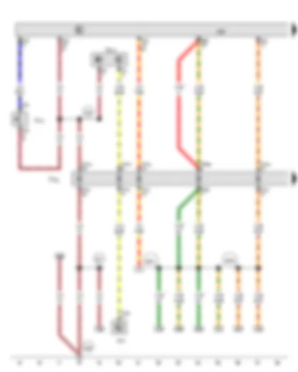
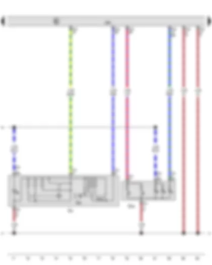
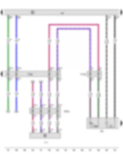
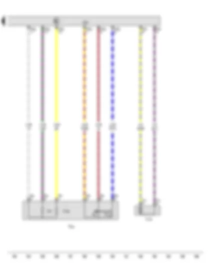
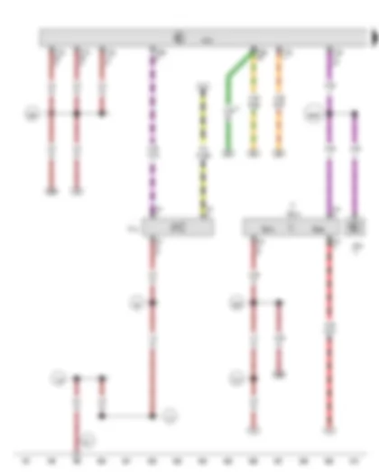
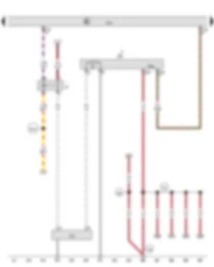
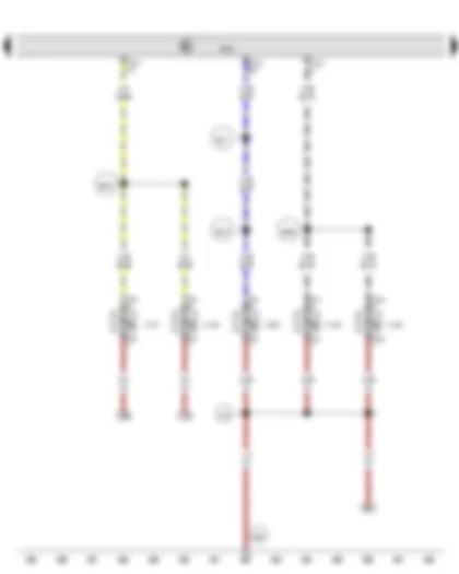
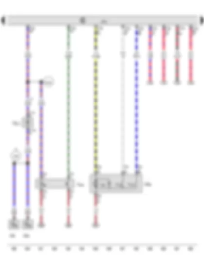
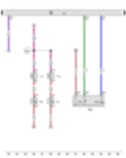
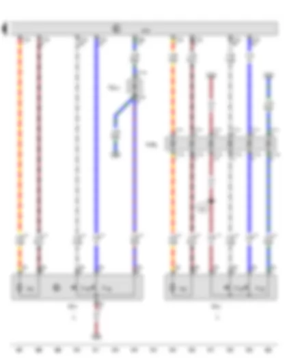
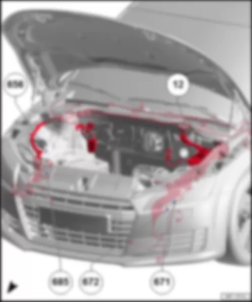
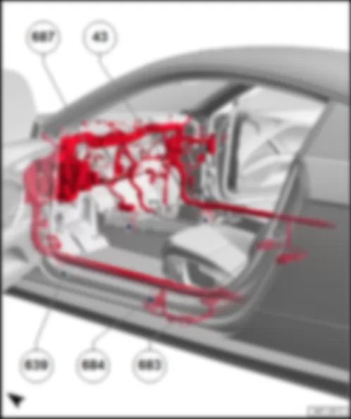
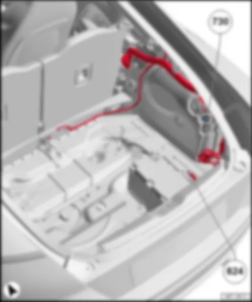
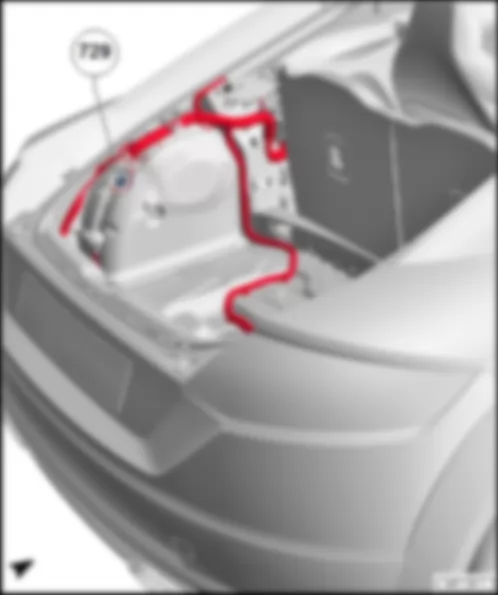
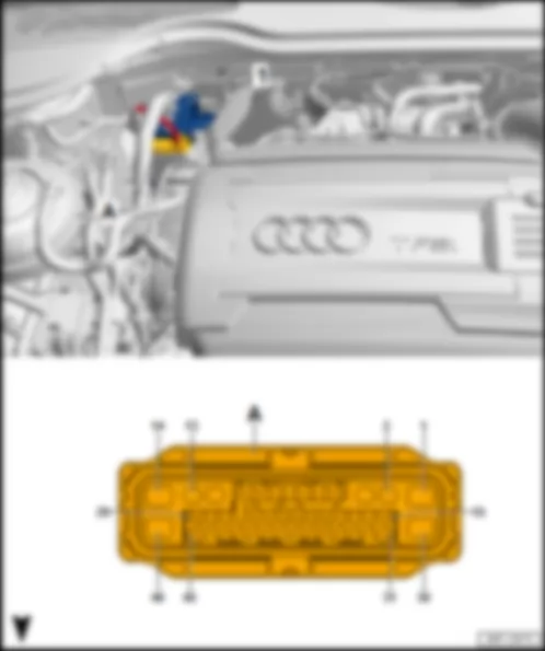
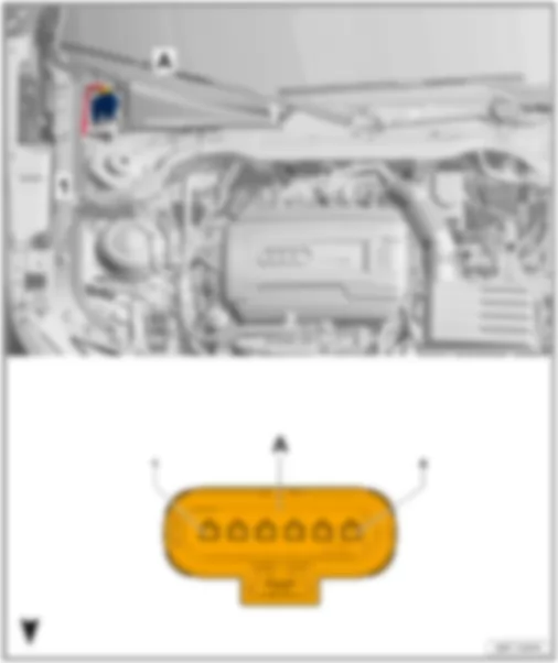
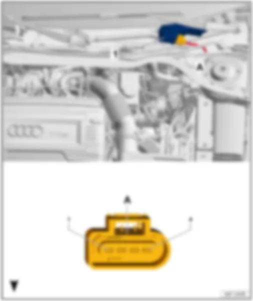
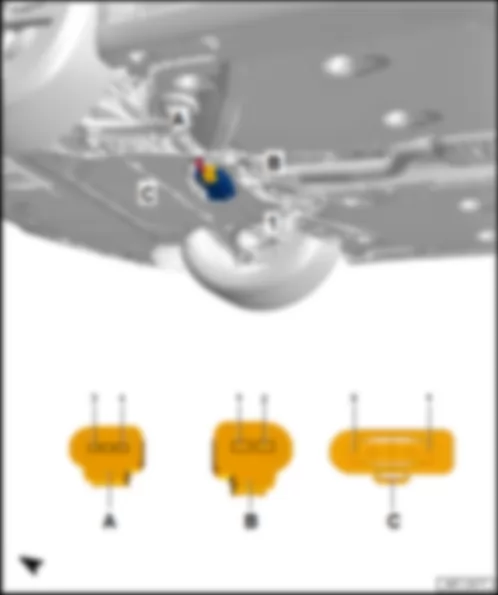
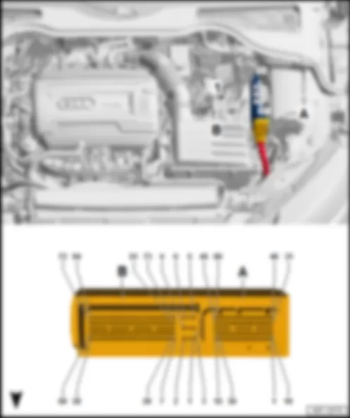
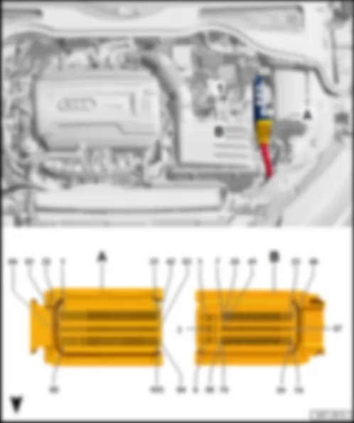
Wiring Diagram AUDI TT 2016 - Fuse holder C

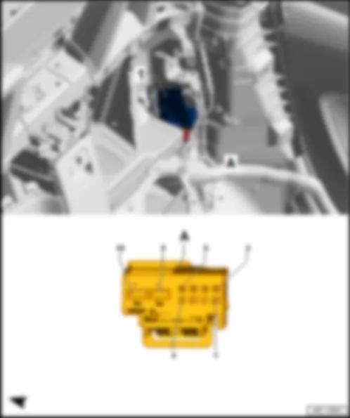
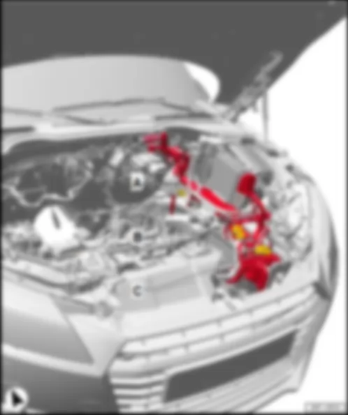
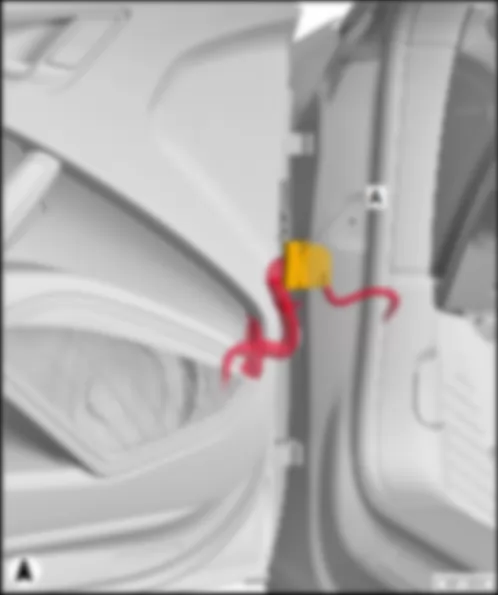
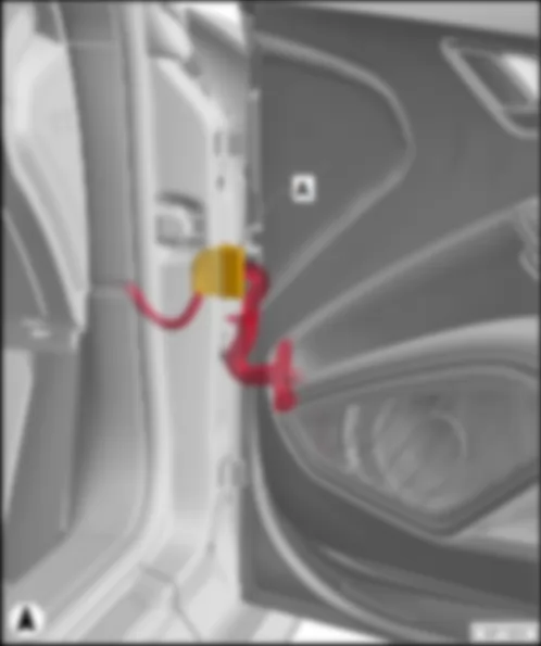
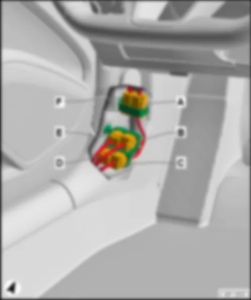
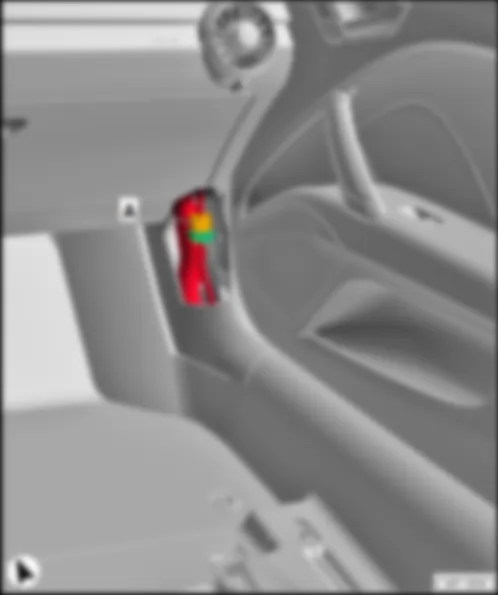
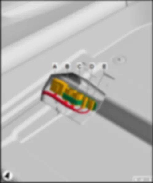
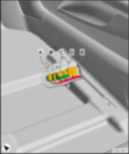
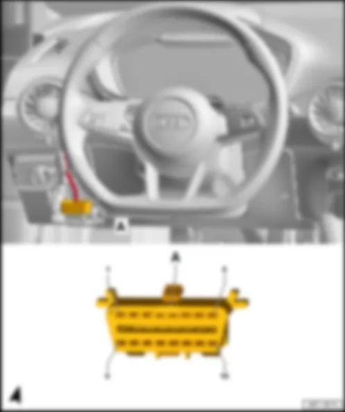
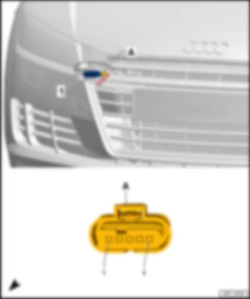
| A | Battery |
| SC | Fuse holder C |
| SC7 | Fuse 7 on fuse holder C |
| SC8 | Fuse 8 on fuse holder C |
| SB20 | Fuse 20 on fuse holder B |
| SC23 | Fuse 23 on fuse holder C |
| SC25 | Fuse 25 on fuse holder C |
| SC26 | Fuse 26 on fuse holder C |
| SC29 | Fuse 29 on fuse holder C |
| SC39 | Fuse 39 on fuse holder C |
| SC42 | Fuse 42 on fuse holder C |
| SC43 | Fuse 43 on fuse holder C |
| S131 | Fuse 1 |
| S132 | Fuse 2 |
| S133 | Fuse 3 |
| B317 | Positive connection 3 (30a) in main wiring harness |
| * | see applicable current flow diagram for fuse assignment |
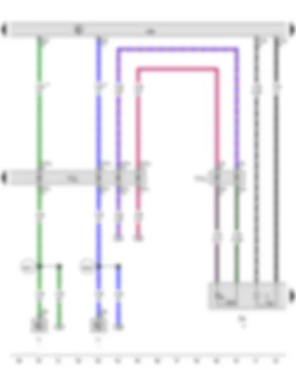
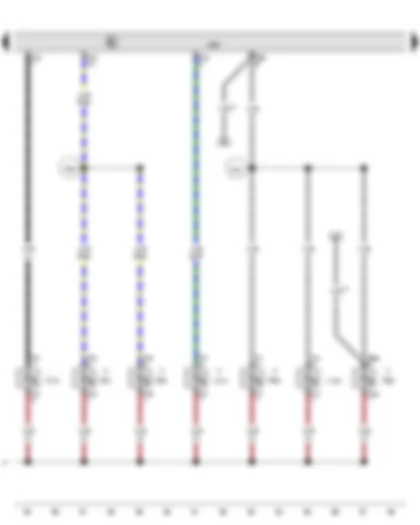
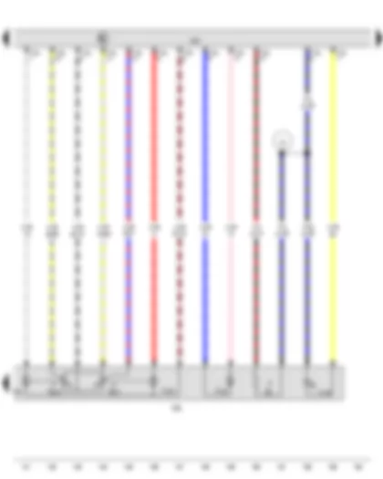
Wiring Diagram AUDI TT 2016 - Driver door exterior handle switch - Driver door exterior handle contact sensor - Driver door control unit
| F272 | Driver door exterior handle switch |
| G415 | Driver door exterior handle contact sensor |
| J386 | Driver door control unit |
| J518 | Entry and start authorisation control unit |
| T2fc | 2-pin connector |
| T2v | 2-pin connector |
| T20f | 20-pin connector |
| T27a | 27-pin connector |
| T27ax | 27-pin connector, black |
| T40a | 40-pin connector |
| TTVL | Coupling point on front left door |
| 205 | Earth connection, in driver door wiring harness |
| 367 | Earth connection 2, in main wiring harness |
| B397 | Connection 1 (convenience CAN bus, high), in main wiring harness |
| B406 | Connection 1 (convenience CAN bus, low), in main wiring harness |
| * | From June 2015 |
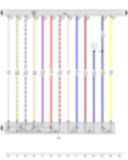
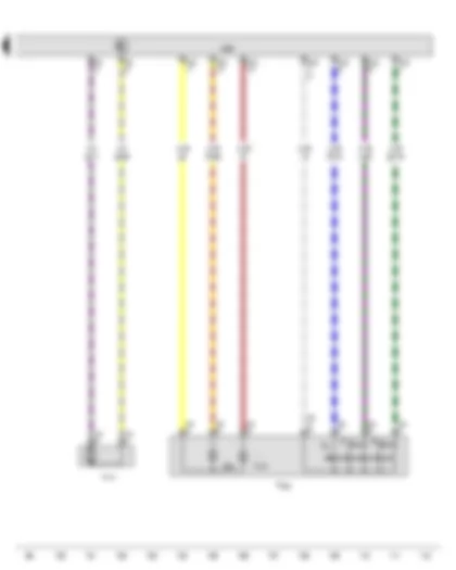
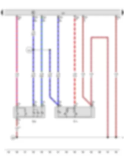
Wiring Diagram AUDI TT 2016 - Driver door control unit - Driver side exterior mirror
| J386 | Driver door control unit |
| K233 | Lane change assist warning lamp in driver side exterior mirror |
| T2k | 2-pin connector |
| T2kx | 2-pin connector |
| T8a | 8-pin connector, black |
| T16b | 16-pin connector |
| T20f | 20-pin connector |
| T27a | 27-pin connector |
| T27ax | 27-pin connector, black |
| TTIVL | Coupling point in front left door |
| TTVL | Coupling point on front left door |
| VX4 | Driver side exterior mirror |
| Y7 | Automatic anti-dazzle interior mirror |
| Y20 | Driver side automatic anti-dazzle exterior mirror |
| B427 | Connection 1 (mirror signal), in main wiring harness |
| B428 | Connection 2 (mirror signal), in main wiring harness |
| * | see applicable current flow diagram for basic equipment |
| *2 | Pre-wired component |
| *3 | Only models with automatic anti-dazzle exterior mirror |
| *4 | Only models with automatic anti-dazzle interior mirror |
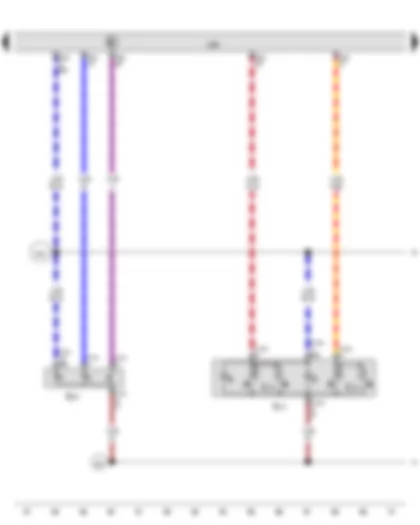
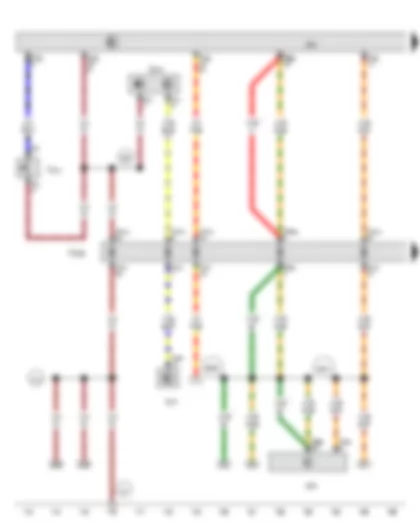
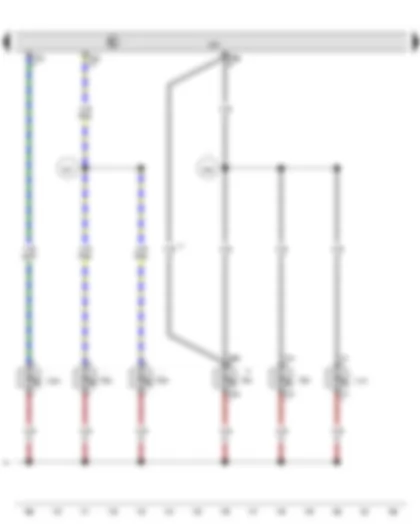
Wiring Diagram AUDI TT 2016 - Potentiometer for horizontal adjustment of driver side mirror - Driver door control unit - Driver side exterior mirror
| G514 | Potentiometer for horizontal adjustment of driver side mirror |
| G515 | Potentiometer for vertical adjustment of driver side mirror |
| J386 | Driver door control unit |
| L131 | Driver side turn signal repeater bulb |
| T16b | 16-pin connector |
| VX4 | Driver side exterior mirror |
| V17 | Driver side mirror adjustment motor 2 |
| V121 | Driver side fold-in mirror motor |
| V149 | Driver side mirror adjustment motor |
| Z4 | Heated exterior mirror on driver side |
| Z1 | Connection 1, in mirror adjustment/heating wiring harness |
| * | According to equipment |
| *2 | Only models with heated exterior mirrors |
| *3 | Only models with electric folding exterior mirrors |
Wiring Diagram AUDI TT 2016 - Operating unit for window regulator in driver door - Button for deactivating interior monitoring and vehicle inclination sensor - Driver door control unit
| E512 | Operating unit for window regulator in driver door |
| E616 | Button for deactivating interior monitoring and vehicle inclination sensor |
| E710 | Front driver side window regulator button |
| E715 | Front passenger side window regulator button, in driver door |
| J386 | Driver door control unit |
| T10m | 10-pin connector |
| T10n | 10-pin connector |
| T32f | 32-pin connector |
| 267 | Earth connection 2, in drive side door wiring harness |
| R52 | Connection (58s), in driver side door wiring harness |
| * | Not for American markets |
Wiring Diagram AUDI TT 2016 - Mirror adjustment switch - Driver side interior locking button for central locking system - Driver door control unit
| E43 | Mirror adjustment switch |
| E48 | Mirror adjustment changeover switch |
| E168 | Adjustment switch for mirror with fold-in feature |
| E308 | Driver side interior locking button for central locking system |
| J386 | Driver door control unit |
| T4o | 4-pin connector |
| T4p | 4-pin connector |
| T32f | 32-pin connector |
| 267 | Earth connection 2, in drive side door wiring harness |
| R52 | Connection (58s), in driver side door wiring harness |
Wiring Diagram AUDI TT 2016 - Driver door control unit - Central locking SAFELOCK function warning lamp - Light for driver side interior door handle illumination - Driver side door warning lamp - Driver side entry light
| J386 | Driver door control unit |
| K133 | Central locking SAFELOCK function warning lamp |
| L160 | Driver door storage compartment illumination bulb |
| L219 | Light for driver side interior door handle illumination |
| T2aa | 2-pin connector |
| T2fd | 2-pin connector |
| T2fe | 2-pin connector |
| T2ff | 2-pin connector |
| T2z | 2-pin connector |
| T4q | 4-pin connector |
| T4r | 4-pin connector |
| T32f | 32-pin connector |
| W30 | Driver side door warning lamp |
| W86 | Light for driver door ambient lighting |
| W92 | Driver side entry light |
| 267 | Earth connection 2, in drive side door wiring harness |
| R65 | Positive connection (58), in driver door wiring harness |
| R94 | Connection 1 in driver side door wiring harness |
| * | Pre-wired component |
| *2 | Only models with additional lights |
| *3 | Only models with Bang & Olufsen sound system |
Wiring Diagram AUDI TT 2016 - Driver side central locking lock unit - Driver door control unit - Driver side window regulator motor
| F2 | Driver door contact switch |
| F131 | Front left central locking actuator |
| F220 | Driver side central locking lock unit |
| F241 | Driver side contact switch in lock cylinder |
| J386 | Driver door control unit |
| T3t | 3-pin connector |
| T6l | 6-pin connector |
| T8f | 8-pin connector, black |
| T20f | 20-pin connector |
| V56 | Driver door central locking motor |
| V147 | Driver side window regulator motor |
| V161 | Driver door central locking SAFELOCK function motor |
| * | Not for American markets |
Wiring Diagram AUDI TT 2016 - Front passenger door exterior handle switch - Front passenger door exterior handle contact sensor - Front passenger door control unit
| F273 | Front passenger door exterior handle switch |
| G416 | Front passenger door exterior handle contact sensor |
| J387 | Front passenger door control unit |
| J518 | Entry and start authorisation control unit |
| J533 | Data bus diagnostic interface |
| T2w | 2-pin connector |
| T2y | 2-pin connector |
| T20a | 20-pin connector, black |
| T20g | 20-pin connector |
| T27b | 27-pin connector, black |
| T27bx | 27-pin connector, black |
| T40a | 40-pin connector |
| TTVR | Coupling point on front right door |
| 206 | Earth connection, in front passenger door wiring harness |
| 373 | Earth connection 8, in main wiring harness |
| B398 | Connection 2 (convenience CAN bus, high), in main wiring harness |
| B407 | Connection 2 (convenience CAN bus, low), in main wiring harness |
| * | From June 2015 |
Wiring Diagram AUDI TT 2016 - Front passenger door control unit - Front passenger side exterior mirror - Front passenger side automatic anti-dazzle exterior mirror
| J387 | Front passenger door control unit |
| J770 | Lane change assist control unit 2 |
| K234 | Lane change assist warning lamp in front passenger side exterior mirror |
| T2l | 2-pin connector |
| T2lx | 2-pin connector |
| T10i | 10-pin connector, black |
| T10ix | 10-pin connector, black |
| T12h | 12-pin connector, black |
| T16c | 16-pin connector |
| T20g | 20-pin connector |
| T27b | 27-pin connector, black |
| T27bx | 27-pin connector, black |
| TSFHL | Coupling point on rear left bumper, in rear bumper |
| TTIVR | Coupling point in front right door |
| TTVR | Coupling point on front right door |
| VX5 | Front passenger side exterior mirror |
| Y21 | Front passenger side automatic anti-dazzle exterior mirror |
| * | Only models with automatic anti-dazzle exterior mirror |
| *2 | Only models with automatic anti-dazzle interior mirror |
Wiring Diagram AUDI TT 2016 - Front passenger door control unit - Front passenger side exterior mirror - Front passenger side mirror adjustment motor 2 - Heated exterior mirror on front passenger side
| G516 | Potentiometer for horizontal adjustment of front passenger side mirror |
| G517 | Potentiometer for vertical adjustment of front passenger side mirror |
| J387 | Front passenger door control unit |
| L132 | Front passenger side turn signal repeater bulb |
| T16c | 16-pin connector |
| VX5 | Front passenger side exterior mirror |
| V25 | Front passenger side mirror adjustment motor 2 |
| V122 | Front passenger side fold-in mirror motor |
| V150 | Front passenger side mirror adjustment motor |
| Z5 | Heated exterior mirror on front passenger side |
| Z2 | Connection 2, in mirror adjustment/heating wiring harness |
| * | Only models with fold-in mirror |
| *2 | Only models with heated exterior mirrors |
| *3 | According to equipment |
Wiring Diagram AUDI TT 2016 - Front passenger side interior locking button for central locking system - Front passenger side window regulator button - Front passenger door control unit
| E309 | Front passenger side interior locking button for central locking system |
| E716 | Front passenger side window regulator button |
| J387 | Front passenger door control unit |
| T4s | 4-pin connector |
| T4t | 4-pin connector |
| T32g | 32-pin connector |
| 268 | Earth connection 2, in front passenger side door wiring harness |
| R53 | Connection (58s), in driver side door wiring harness |
| * | Only for American markets |
| *2 | Only models with additional lights |
Wiring Diagram AUDI TT 2016 - Front passenger door control unit - Light for passenger side interior door handle illumination - Front passenger side door warning lamp - Passenger side entry light
| J387 | Front passenger door control unit |
| L161 | Front passenger door storage compartment illumination bulb |
| L220 | Light for passenger side interior door handle illumination |
| T2ab | 2-pin connector |
| T4bv | 4-pin connector |
| T4u | 4-pin connector |
| T32g | 32-pin connector |
| W36 | Front passenger side door warning lamp |
| W87 | Light for passenger door ambient lighting |
| W93 | Passenger side entry light |
| 268 | Earth connection 2, in front passenger side door wiring harness |
| R67 | Positive connection (58), in front passenger door wiring harness |
| R98 | Connection 1 in front passenger side door wiring harness |
| * | Only models with additional lights |
| *2 | Only models with Bang & Olufsen sound system |
| *3 | Only models with no additional lights |
Wiring Diagram AUDI TT 2016 - Front passenger side central locking lock unit - Front passenger door control unit - Front passenger side window regulator motor
| F3 | Front passenger door contact switch |
| F133 | Front right central locking actuator |
| F221 | Front passenger side central locking lock unit |
| J387 | Front passenger door control unit |
| T3u | 3-pin connector |
| T6m | 6-pin connector |
| T6n | 6-pin connector |
| T20g | 20-pin connector |
| V57 | Front passenger seat central locking motor |
| V148 | Front passenger side window regulator motor |
| V162 | Front passenger door central locking SAFELOCK function motor |
| * | Not for American markets |
Wiring Diagram AUDI TT 2016 - Anti-theft alarm sensor - Alarm horn - Onboard supply control unit
| G273 | Interior monitoring sensor |
| G384 | Vehicle inclination sender |
| G578 | Anti-theft alarm sensor |
| H12 | Alarm horn |
| J519 | Onboard supply control unit |
| J530 | Garage door operation control unit |
| T3v | 3-pin connector, black |
| T4d | 4-pin connector, black |
| T46a | 46-pin connector, black |
| T73a | 73-pin connector, black |
| T73c | 73-pin connector, black |
| 85 | Earth connection 1, in engine compartment wiring harness |
| 131 | Earth connection 2, in engine compartment wiring harness |
| 132 | Earth connection 3, in engine compartment wiring harness |
| 366 | Earth connection 1, in main wiring harness |
| 369 | Earth connection 4, in main wiring harness |
| 370 | Earth connection 5, in main wiring harness |
| B528 | Connection 1 (LIN bus) in main wiring harness |
| * | For models with anti-theft alarm system |
| *2 | Only models with anti-theft alarm system and tow-away protection |
| *3 | see applicable current flow diagram |
| *4 | From June 2015 |
Wiring Diagram AUDI TT 2016 - Onboard supply control unit - Heated rear window - Rear window
| C18 | Window aerial suppression filter |
| G304 | Glass breakage sensor for rear window |
| J9 | Heated rear window relay |
| J519 | Onboard supply control unit |
| T2ac | 2-pin connector |
| T73a | 73-pin connector, black |
| T73c | 73-pin connector, black |
| Z1 | Heated rear window |
| ZX1 | Rear window |
| 374 | Earth connection 9, in main wiring harness |
| 380 | Earth connection 15, in main wiring harness |
| B316 | Positive connection 2 (30a) in main wiring harness |
| * | Coupé |
| *2 | Pre-wired component |
Wiring Diagram AUDI TT 2016 - Onboard supply control unit - Front left footwell illumination bulb - Light 1 for front centre console background lighting - Light 1 for contour lighting of multimedia system operating unit
| J519 | Onboard supply control unit |
| L151 | Front left footwell illumination bulb |
| L152 | Front right footwell illumination bulb |
| L193 | Light 1 for front centre console background lighting |
| L194 | Light 2 for front centre console background lighting |
| L233 | Light 1 for contour lighting of multimedia system operating unit |
| T2fh | 2-pin connector |
| T2fi | 2-pin connector |
| T2fl | 2-pin connector |
| T4bd | 4-pin connector |
| T4w | 4-pin connector |
| T73c | 73-pin connector, black |
| 372 | Earth connection 7, in main wiring harness |
| B371 | Connection 1 (aerial), in main wiring harness |
| B372 | Connection 2 (aerial), in main wiring harness |
| B433 | Connection (footwell light), in main wiring harness |
| B465 | Connection 1, in main wiring harness |
Wiring Diagram AUDI TT 2016 - Release button for rear lid lock cylinder - Onboard supply control unit - Rear lid lock unit
| F123 | Rear lid contact switch for anti-theft alarm |
| F124 | Contact switch in lock cylinder for rear lid, anti-theft alarm system and central locking system |
| F248 | Release button for rear lid lock cylinder |
| J519 | Onboard supply control unit |
| MX1 | Front left headlight |
| MX2 | Front right headlight |
| T4y | 4-pin connector |
| T4z | 4-pin connector |
| T17a | 17-pin connector, white |
| T17ex | 17-pin connector, red |
| T73a | 73-pin connector, black |
| T73c | 73-pin connector, black |
| TALU | Coupling point on left A-pillar, bottom |
| VX25 | Rear lid lock unit |
| V53 | Rear lid central locking motor |
| B132 | Connection (number plate lights), in interior wiring harness |
| C65 | Positive connection 1, in side marker light wiring harness |
| * | Coupé |
| *2 | Only for American markets |
Wiring Diagram AUDI TT 2016 - Centre switch module in dash panel - Adjustable rear spoiler switch - Driver vanity mirror contact switch - Front passenger vanity mirror contact switch - Onboard supply control unit - Front passenger side illuminated vanity mirror - Driver side illuminated vanity mirror
| EX22 | Centre switch module in dash panel |
| E127 | Adjustable rear spoiler switch |
| F147 | Driver vanity mirror contact switch |
| F148 | Front passenger vanity mirror contact switch |
| J519 | Onboard supply control unit |
| K242 | Rear spoiler position warning lamp |
| T2cj | 2-pin connector |
| T2ha | 2-pin connector |
| T2hb | 2-pin connector |
| T2hc | 2-pin connector |
| T20b | 20-pin connector |
| T73a | 73-pin connector, black |
| T73c | 73-pin connector, black |
| W14 | Front passenger side illuminated vanity mirror |
| W20 | Driver side illuminated vanity mirror |
| B559 | Positive connection 1 (30g) in main wiring harness |
| * | Coupé |
| *2 | Only models with electrically adjustable rear spoiler |
Wiring Diagram AUDI TT 2016 - Onboard supply control unit - Rear spoiler
| F135 | Rear spoiler adjustment limit switch 1 |
| F136 | Rear spoiler adjustment limit switch 2 |
| J519 | Onboard supply control unit |
| T8t | 8-pin connector |
| T17d | 17-pin connector |
| T17dx | 17-pin connector |
| T17k | 17-pin connector |
| T17kx | 17-pin connector |
| T46a | 46-pin connector, black |
| T73a | 73-pin connector, black |
| TALU | Coupling point on left A-pillar, bottom |
| THRL | Coupling point in luggage compartment, left |
| V52 | Adjustable rear spoiler motor |
| VX73 | Rear spoiler |
| 98 | Earth connection, in rear lid wiring harness |
| * | Pre-wired component |
| *2 | Coupé |
| *3 | Roadster |
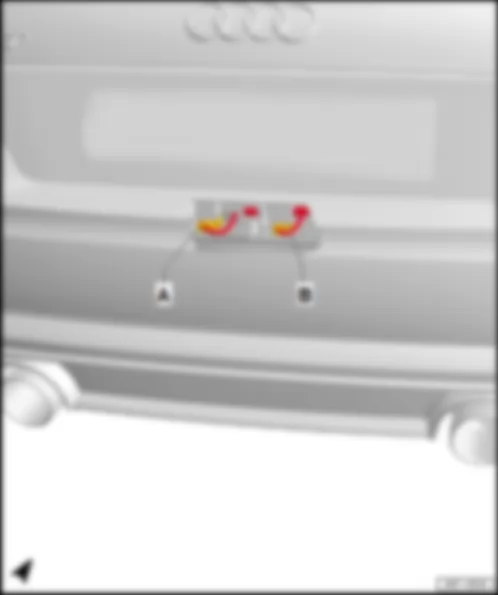
| *4 | Only models with electrically adjustable rear spoiler |
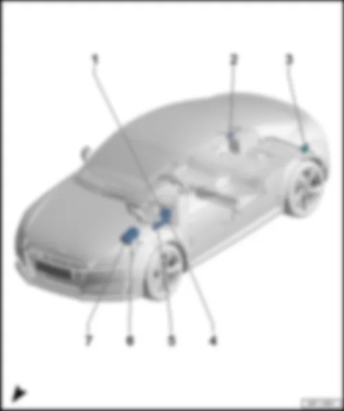
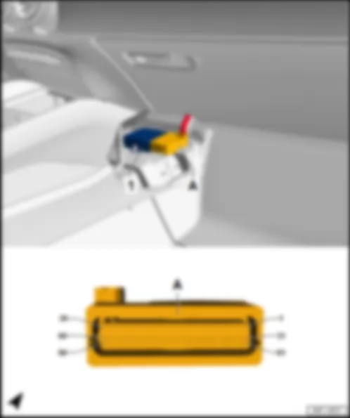
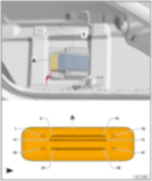
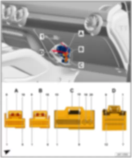
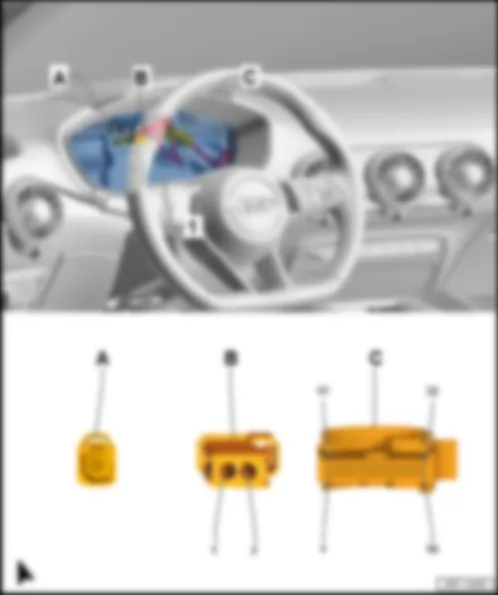
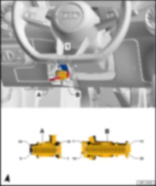
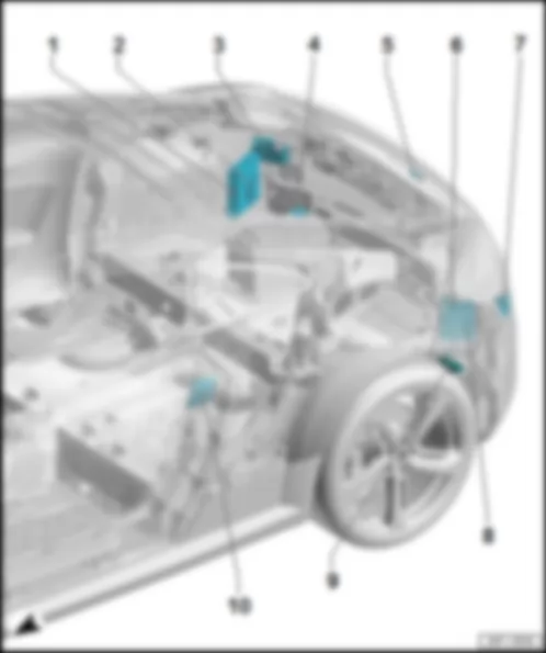
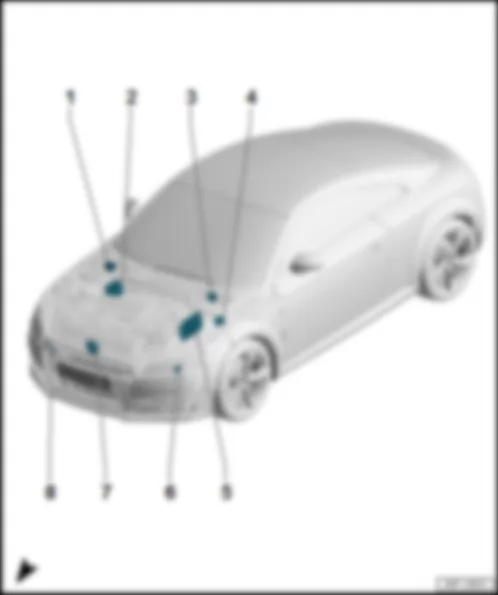
AUDI TT 2016 Overview of fuses
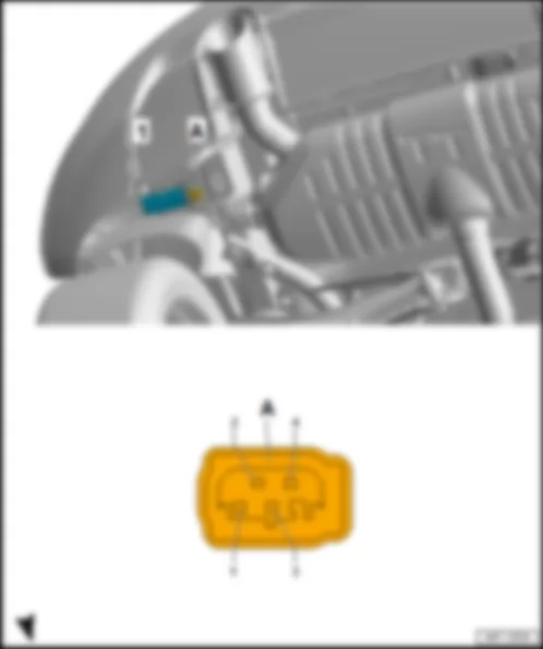
| Jump start connection -TV32- /wiring junction -TV1- |
| q | Fitting location |
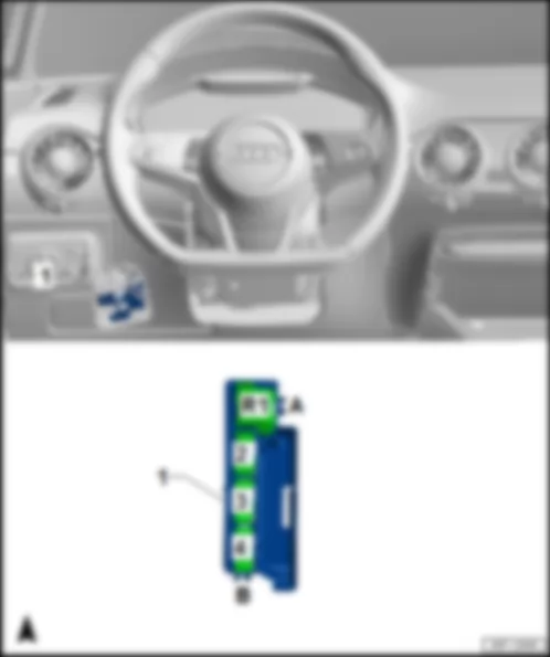
| Relay and fuse carrier 4 -SR4- |
| t | Fuse holder D -SD- |
| t | Fuse holder F -SF- |
| q | Fitting location |
| q | Fuse assignment on fuse holder D -SD- |
| q | Fuse assignment on fuse holder F -SF- |
| q | Fitting location, right-hand drive models |
| q | Fuse assignment on fuse holder C -SC- |
| q | Fitting location and fuse assignment, right-hand drive models |
| q | Fuse assignment on fuse holder B -SB- |
| q | Fuse assignment |
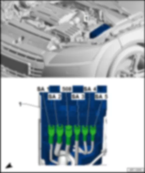
| Fitting location, fuse holder A -SA- |
| 1 - | Fuse holder A -SA- |
| q | Fuse assignment |
| 508 | Threaded connection (30) on electronics box, B1 |
|
| Fuse assignment on fuse holder A -SA- |
| No. | Current Flow Diagram designation | Nominal value | Function/component | Terminal | ||
| J1A | - | Fuse 1 on fuse holder A -SA1- | 125 A | - | not assigned | 30 |
| G1A | - | Fuse 2 on fuse holder A -SA2- | 400 A | - | Alternator -C- | 30 |
| E1A | - | Fuse 3 on fuse holder A -SA3- | 80 A | - | Power steering control unit -J500- | 30 |
| K2A | - | Fuse 4 on fuse holder A -SA4- | 80 A | - | not assigned | 30 |
| L1A | - | Fuse 5 on fuse holder A -SA5- | 50 A | - | Radiator fan control unit -J293- | 30 |
|
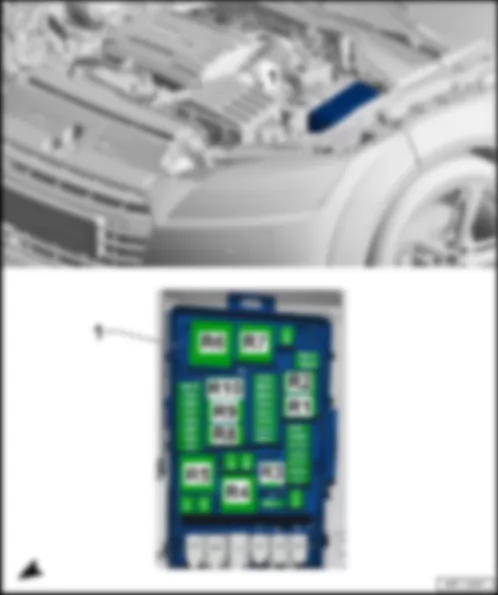
| Fitting location, relay and fuse carrier 1 -SR1- |
| 1 - | Fuse holder B -SB- |
| q | Fuse assignment |
| Fuse colours, J-Case fuse |
| t | 50 A - red |
| t | 40 A - green |
| t | 30 A - pink |
| Fuse colours, ATO flat fuse |
| t | 40 A - orange |
| t | 30 A - light green |
| t | 25 A - clear |
| t | 20 A - yellow |
| t | 15 A - light blue |
| t | 10 A - red |
| t | 7.5 A - brown |
| t | 5 A - light brown |
| t | 1 A - black |
|
| Fuse assignment on fuse holder B -SB- |
| No. | Current Flow Diagram designation | Nominal value | Function/component | Terminal | ||
| 1 | - | not assigned | - | |||
| 2 | - | not assigned | - | |||
| 3 | - | Fuse 3 on fuse holder B -SB3- | 5 A | - | Engine control unit -J623- | 30 |
| 4 | - | Fuse 4 on fuse holder B -SB4- | 10 A1) 3) 4) 5 A2) | - | Oil level and oil temperature sender -G266- Radiator fan control unit -J293- Charge pressure control solenoid valve -N75-2) Low heat output relay -J359-2) High heat output relay -J360-2) Turbocharger air recirculation valve -N249-1) 3) 4) Intake manifold flap valve -N316-1) 3) 4) Valve for oil pressure control -N428-1) 3) 4) Piston cooling jet control valve -N522-1) 3) 4) Secondary air pump relay -J299-1) 3) | 87 |
| 5 | - | Fuse 5 on fuse holder B -SB5- | 10 A | - | Fuel pressure regulating valve -N276-2) Fuel metering valve -N290-2) Camshaft control valve 1 -N205-2) Engine component current supply relay 2 -J976-1) 3) 4) Injector for cylinder -N532- … -N535-1) 3) 4) Actuator for camshaft adjustment -F366- … -F373-1) 3) 4) | 87 |
| 6 | - | Fuse 6 on fuse holder B -SB6- | 5 A | - | Brake light switch -F- /brake pedal switch -F63- | 87 |
| 7 | - | Fuse 7 on fuse holder B -SB7- | 7.5 A1) 3) 4) 10 A2) | - | Coolant shut-off valve -N82-1) 3) 4) Coolant valve for gearbox -N488-1) 3) 4) 5) Coolant circulation pump -V50-1) 3) 4) Valve for oil pressure control -N428-2) Coolant valve for cylinder head -N489-2) Charge air cooling pump -V188-2) Auxiliary pump for heating -V488-2) | 87 |
| 8 | - | Fuse 8 on fuse holder B -SB8- | 15 A1) 3) 4) 10 A2) | - | Lambda probe heater -Z19- Lambda probe 1 heater after catalytic converter -Z29- | 87 |
| 9 | - | Fuse 9 on fuse holder B -SB9- | 10 A1) 3) 4) 5 A2) | - | Air mass meter -G70-2) Heater element for crankcase breather -N79-2) Automatic glow period control unit -J179-2) Continued coolant circulation pump -V51-1) 3) 4) Activated charcoal filter solenoid valve 1 -N80-1) 3) 4) Camshaft control valve 1 -N205-1) 3) 4) Exhaust camshaft control valve 1 -N318-1) 3) 4) Exhaust flap control unit -J883-1) 3) Exhaust flap control unit 2 -J945-1) 3) | 87 |
| 10 | - | Fuse 10 on fuse holder B -SB10- | 15 A1) 3) 4) 20 A2) | - | Fuel pump control unit -J538- | 87 |
| 11 | - | Fuse 11 on fuse holder B -SB11- | 40 A2) 50 A1) 3) | - | Auxiliary air heater element -Z35-2) Secondary air pump motor -V101-1) 3) | 87 |
| 12 | - | Fuse 12 on fuse holder B -SB12- | 40 A2) | - | Auxiliary air heater element -Z35-2) | 87 |
| 13 | - | Fuse 13 on fuse holder B -SB13- | 15 A | - | Mechatronic unit for dual clutch gearbox -J743- | 30 |
| 14 | - | not assigned | - | |||
| 15 | - | Fuse 15 on fuse holder B -SB15- | 15 A | - | Horn relay -J413- Treble horn -H2- Bass horn -H7- | 30 |
| 16 | - | Fuse 16 on fuse holder B -SB16- | 20 A | - | Engine component current supply relay 2 -J976-1) 3) 4) | 30 |
| 17 | - | Fuse 17 on fuse holder B -SB17- | 10 A | - | Suppression filter -C24- | 30 |
| 18 | - | Fuse 18 on fuse holder B -SB18- | 5 A | - | Garage door operation control unit -J530- | 30 |
| 19 | - | Fuse 19 on fuse holder B -SB19- | 30 A | - | Wiper motor control unit -J400- | 30 |
| 20 | - | Fuse 20 on fuse holder B -SB20- | 10 A | - | Alarm horn -H12- | 30 |
| 21 | - | not assigned | - | |||
| 22 | - | Fuse 22 on fuse holder B -SB22- | 5 A | - | Engine control unit -J623- | 50 |
| 23 | - | Fuse 23 on fuse holder B -SB23- | 30 A | - | Starter -B- | 50 |
| 24 | - | Fuse 24 on fuse holder B -SB24- | 40 A2) | - | Auxiliary air heater element -Z35-2) | 87 |
| 25 | - | not assigned | - | |||
| 26 | - | not assigned | - | |||
| 27 | - | not assigned | - | |||
| 28 | - | not assigned | - | |||
| 29 | - | not assigned | - | |||
| 30 | - | not assigned | - | |||
| 31 | - | not assigned | - | |||
| 32 | - | not assigned | - | |||
| 33 | - | not assigned | - | |||
| 34 | - | not assigned | - | |||
| 35 | - | not assigned | - | |||
| 36 | - | not assigned | - | |||
| 37 | - | not assigned | - | |||
| 38 | - | not assigned | - |
| t | 1) models with engine code CHHC, CNTC only |
| t | 2) models with engine code CUNA only |
| t | 3) models with engine code CJXF, CJXG, CYFB only |
| t | 4) models with engine code CJSA only |
| t | 5) models with all-wheel drive only |
|
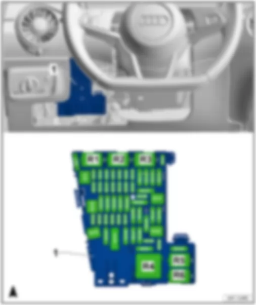
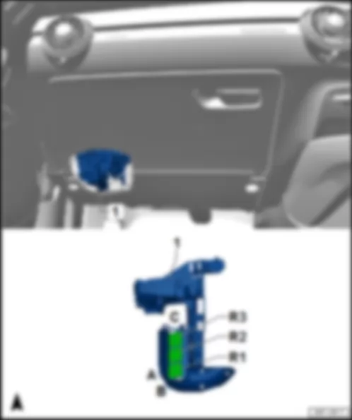
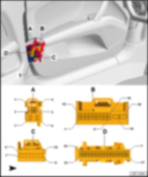
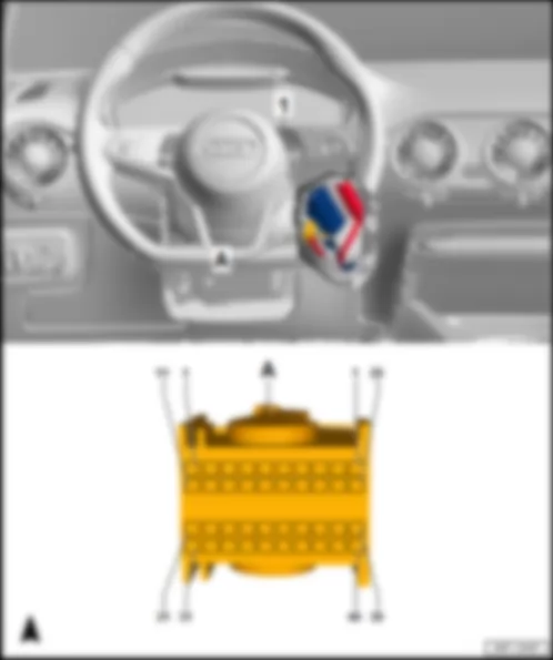
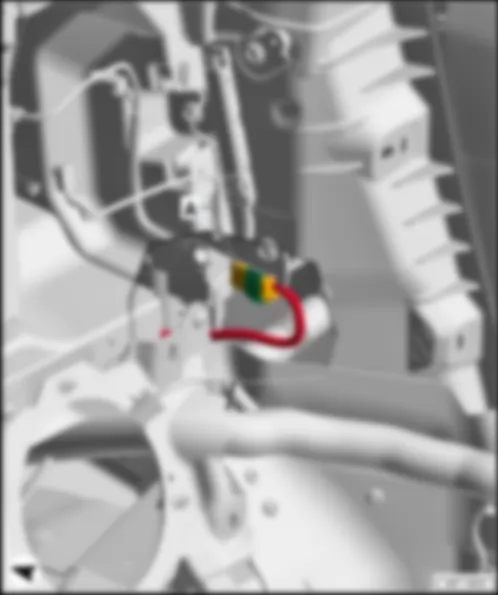
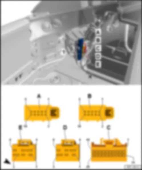
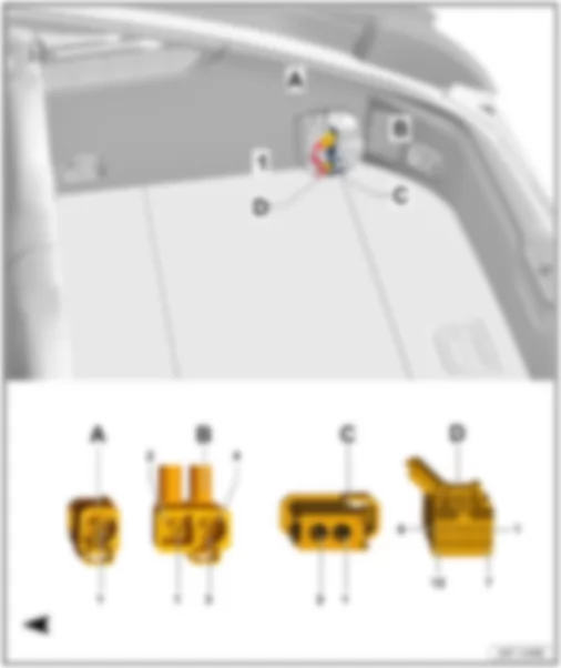
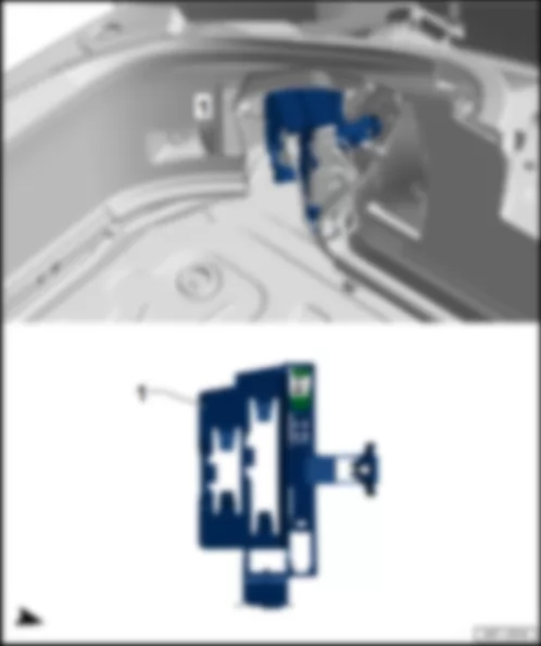
| Fitting location, relay and fuse carrier 2 -SR2- |
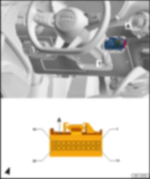
| Fitting location, relay and fuse carrier 2 -SR2- , left-hand drive models |
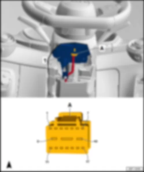
| 1 - | Fuse holder C -SC- |
| q | Fuse assignment |
| Fuse colours, J-Case fuse |
| t | 50 A - red |
| t | 40 A - green |
| t | 30 A - pink |
| Fuse colours, ATO flat fuse |
| t | 40 A - orange |
| t | 30 A - light green |
| t | 25 A - clear |
| t | 20 A - yellow |
| t | 15 A - light blue |
| t | 10 A - red |
| t | 7.5 A - brown |
| t | 5 A - light brown |
| t | 1 A - black |
|
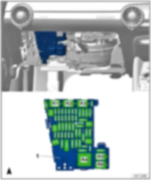
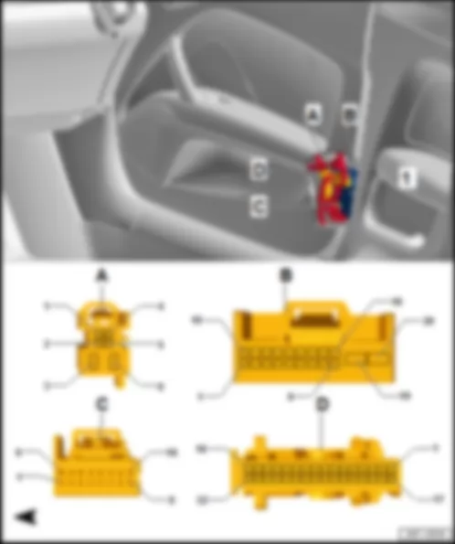
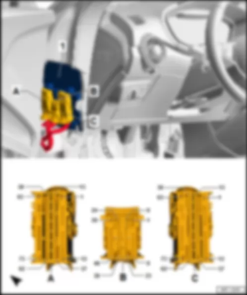
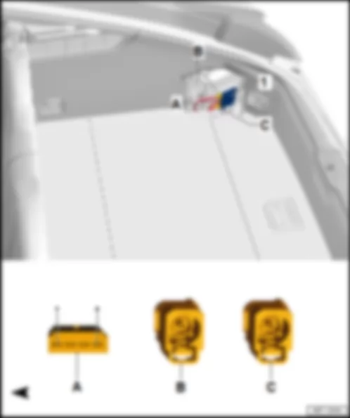
| Fitting location, relay and fuse carrier 2 -SR2- , right-hand drive models |
| 1 - | Fuse holder C -SC- |
| q | Fuse assignment |
| Fuse colours, J-Case fuse |
| t | 50 A - red |
| t | 40 A - green |
| t | 30 A - pink |
| Fuse colours, ATO flat fuse |
| t | 40 A - orange |
| t | 30 A - light green |
| t | 25 A - clear |
| t | 20 A - yellow |
| t | 15 A - light blue |
| t | 10 A - red |
| t | 7.5 A - brown |
| t | 5 A - light brown |
| t | 1 A - black |
|
| Fuse assignment, fuse holder C -SC- |
| No. | Current Flow Diagram designation | Nominal value | Function/component | Terminal | ||
| 1 | - | Fuse 1 on fuse holder C -SC1- | 30 A | - | Control unit for reducing agent metering system -J880- | 30 |
| 2 | - | not assigned | - | |||
| 3 | - | Fuse 3 on fuse holder C -SC3- | 40 A | - | ABS control unit -J104- | 30 |
| 4 | - | Fuse 4 on fuse holder C -SC4- | 7.5 A | - | Control unit 1 for information electronics -J794- Multimedia system operating unit -E380- | 30 |
| 5 | - | Fuse 5 on fuse holder C -SC5- | 5 A | - | Data bus diagnostic interface -J533- | 30 |
| 6 | - | Fuse 6 on fuse holder C -SC6- | 5 A | - | Selector lever sensors control unit -J587- Anti-theft alarm sensor -G578- | 30 |
| 7 | - | Fuse 7 on fuse holder C -SC7- | 10 A | - | Climatronic control unit -J255- Heated rear window relay -J9- Tyre Pressure Monitoring System control unit -J502- | 30 |
| 8 | - | Fuse 8 on fuse holder C -SC8- | 10 A | - | Light switch -E1- Electromechanical parking brake button -E538- Diagnostic connection -U31- Roof electronics control unit -J528- Light and rain sensor -G397- | 30 |
| 9 | - | Fuse 9 on fuse holder C -SC9- | 1 A | - | Steering column electronics control unit -J527- | 30 |
| 10 | - | not assigned | - | |||
| 11 | - | Fuse 11 on fuse holder C -SC11- | 15 A | - | All-wheel drive control unit -J492- | 30 |
| 12 | - | Fuse 12 on fuse holder C -SC12- | 20 A 30 A | - | Control unit 1 for information electronics -J794- Digital sound package control unit -J525- | 30 |
| 13 | - | Fuse 13 on fuse holder C -SC13- | 20 A | - | Electronically controlled damping control unit -J250- | 30 |
| 14 | - | Fuse 14 on fuse holder C -SC14- | 30 A | - | Fresh air blower control unit -J126- | 30 |
| 15 | - | Fuse 15 on fuse holder C -SC15- | 10 A | - | Control unit for electronic steering column lock -J764- | 30 |
| 16 | - | Fuse 16 on fuse holder C -SC16- | 7.5 A | - | TV tuner -R78- Aerial amplifier for mobile telephone -R86- Telephone bracket -R126- Chip card reader control unit -J676- | 30 |
| 17 | - | Fuse 17 on fuse holder C -SC17- | 10 A | - | Control unit in dash panel insert -J285- | 30 |
| 18 | - | Fuse 18 on fuse holder C -SC18- | 7.5 A | - | Interface control unit for vehicle location system -J843- Reversing camera system control unit -J772- | 30 |
| 19 | - | Fuse 19 on fuse holder C -SC19- | 7.5 A | - | Entry and start authorisation control unit -J518- | 30 |
| 20 | - | Fuse 20 on fuse holder C -SC20- | 10 A | - | Front left seat Front right seat | 30 |
| 21 | - | not assigned | - | |||
| 22 | - | Fuse 22 on fuse holder C -SC22- | 5 A | - | Control unit for right neck heating -J847-1) | 30 |
| 23 | - | Fuse 23 on fuse holder C -SC23- | 40 A | - | Onboard supply control unit -J519- | 30 |
| 24 | - | - | ||||
| 25 | - | Fuse 25 on fuse holder C -SC25- | 30 A | - | Driver door control unit -J386- | 30 |
| 26 | - | Fuse 26 on fuse holder C -SC26- | 30 A | - | Onboard supply control unit -J519- | 30 |
| 27 | - | not assigned | - | |||
| 28 | - | Fuse 28 on fuse holder C -SC28- | 5 A | - | Connection for external audio sources -R199- | 30 |
| 29 | - | Fuse 29 on fuse holder C -SC29- | 7.5 A | - | Glove compartment light switch -E26- Driver vanity mirror contact switch -F147- Front passenger vanity mirror contact switch -F148- Roof electronics control unit -J528- Front roof module -WX3- | 30 |
| 30 | - | not assigned | - | |||
| 31 | - | Fuse 31 on fuse holder C -SC31- | 40 A | - | Onboard supply control unit -J519- | 30 |
| 32 | - | Fuse 32 on fuse holder C -SC32- | 7.5 A | - | Lane change assist control unit -J769- Lane change assist control unit 2 -J770- Parking aid control unit -J446- Park assist steering control unit -J791- Front camera for driver assist systems -R242- | 15 |
| 33 | - | Fuse 33 on fuse holder C -SC33- | 5 A | - | Airbag control unit -J234- Roof electronics control unit -J528- Seat occupied recognition control unit -J706- | 15 |
| 34 | - | Fuse 34 on fuse holder C -SC34- | 7.5 A | - | Electromechanical parking brake button -E538- Auto-hold button -E540- Reversing light switch -F4- Pressure sender for refrigerant circuit -G805- Garage door operation control unit -J530- Relay for power sockets -J807- Relay for neck heating -J989-1) | 15 |
| 35 | - | Fuse 35 on fuse holder C -SC35- | 10 A | - | Operating unit in front of centre console -E461- Air quality sensor -G238- Headlight range control unit -J431- Diagnostic connection -U31- Automatic anti-dazzle interior mirror -Y7- | 15 |
| 36 | - | Fuse 36 on fuse holder C -SC36- | 15 A | - | Front right headlight -MX2- | 15 |
| 37 | - | Fuse 37 on fuse holder C -SC37- | 15 A | - | Front left headlight -MX1- | 15 |
| 38 | - | Fuse 38 on fuse holder C -SC38- | 7.5 A | - | Main relay -J271- Terminal 30 voltage supply relay -J317- Engine control unit -J623- ABS control unit -J104- | 30 |
| 39 | - | Fuse 39 on fuse holder C -SC39- | 30 A | - | Front passenger door control unit -J387- | 30 |
| 40 | - | Fuse 40 on fuse holder C -SC40- | 20 A | - | 12 V socket -U5- 12 V socket 2 -U18- | 30 |
| 41 | - | Fuse 41 on fuse holder C -SC41- | 7.5 A | - | Control unit for fuel tank leak detection -J909-2) Relay for reducing agent metering system -J963-3) | 30 |
| 42 | - | Fuse 42 on fuse holder C -SC42- | 40 A | - | Onboard supply control unit -J519- | 30 |
| 43 | - | Fuse 43 on fuse holder C -SC43- | 30 A | - | Onboard supply control unit -J519- | 30 |
| 44 | - | not assigned | - | |||
| 45 | - | Fuse 45 on fuse holder C -SC45- | 15 A | - | Front left seat | 30 |
| 46 | - | Fuse 46 on fuse holder C -SC46- | 30 A | - | Control unit for left neck heating -J846-1) | 30 |
| 47 | - | not assigned | - | |||
| 48 | - | not assigned | - | |||
| 49 | - | Fuse 49 on fuse holder C -SC49- | 5 A | - | Clutch position sender -G476- Starter relay 1 -J906- Starter relay 2 -J907- | 15 |
| 50 | - | Fuse 50 on fuse holder C -SC50- | 40 A | - | ABS control unit -J104- | 30 |
| 51 | - | not assigned | - | |||
| 52 | - | not assigned | - | |||
| 53 | - | not assigned | - |
| 1) roadster only |
| 2) for models with US equipment only |
| 3) for models with SCR system only |
|
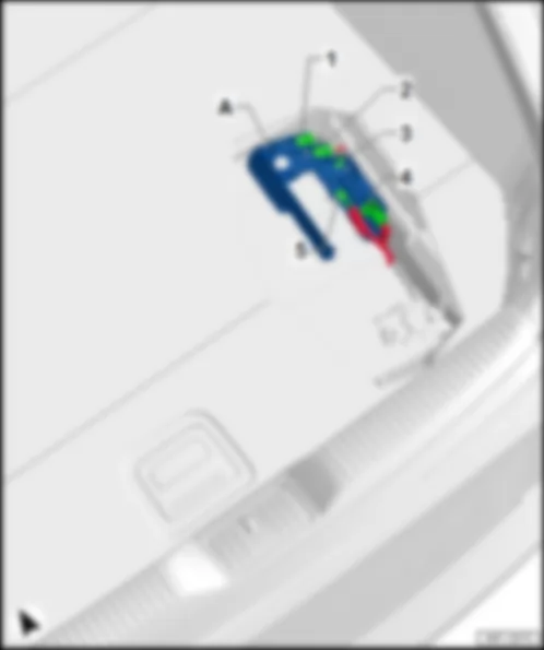
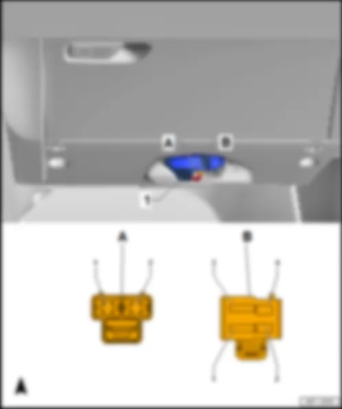
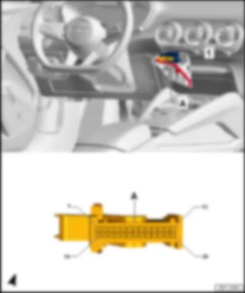
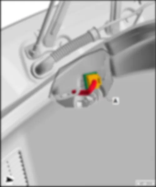
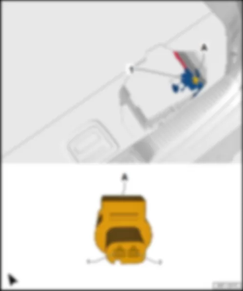
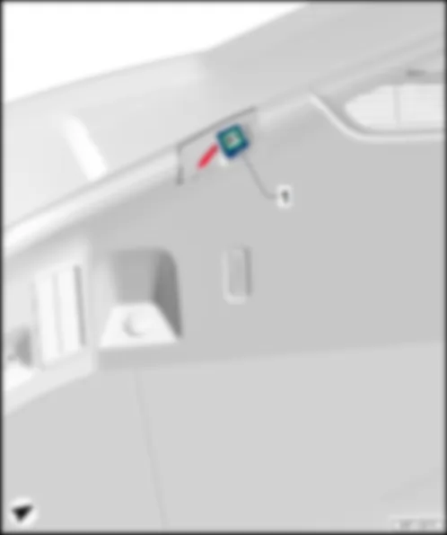
| Fitting location, relay and fuse carrier 3 -SR3- |
| Fitting location, relay and fuse carrier 3 -SR3- , left-hand drive models |
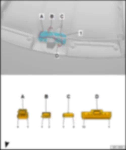
| 1 - | Relay and fuse carrier 3 -SR3- |
| A - | Front passenger seat adjustment thermal fuse 1 -S46- , 15 A, light blue |
| B - | not assigned |
|
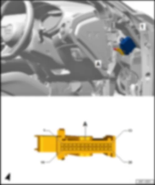
| Fitting location, relay and fuse carrier 3 -SR3- , right-hand drive models |
| 1 - | Relay and fuse carrier 3 -SR3- |
| A - | Front passenger seat adjustment thermal fuse 1 -S46- , 15 A, light blue |
| B - | not assigned |
| C - | not assigned |
|
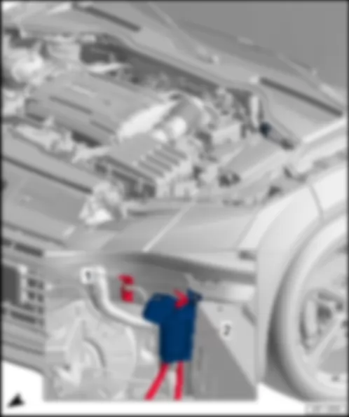
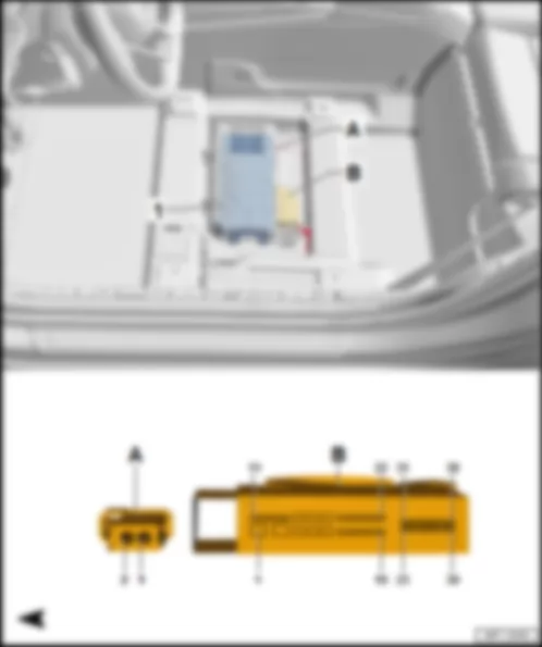
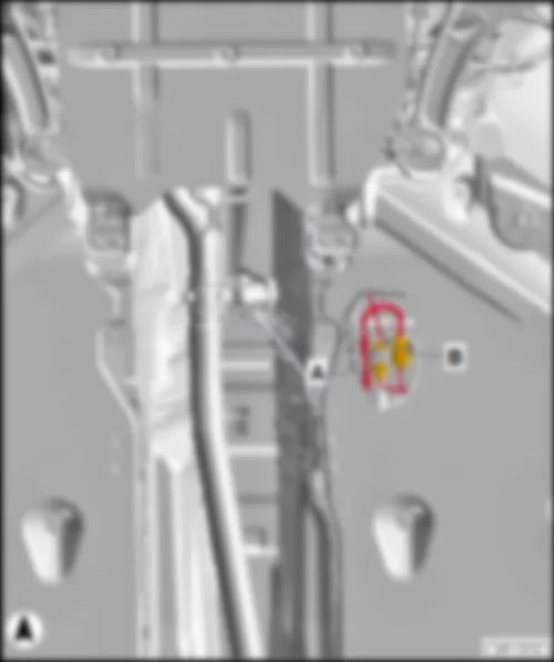
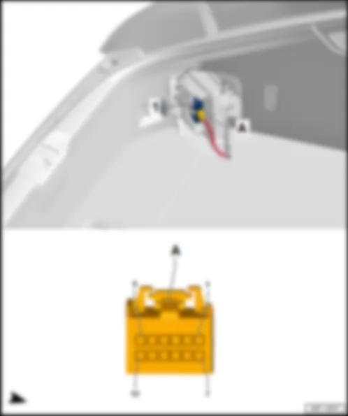
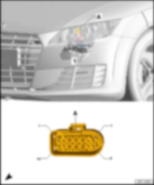
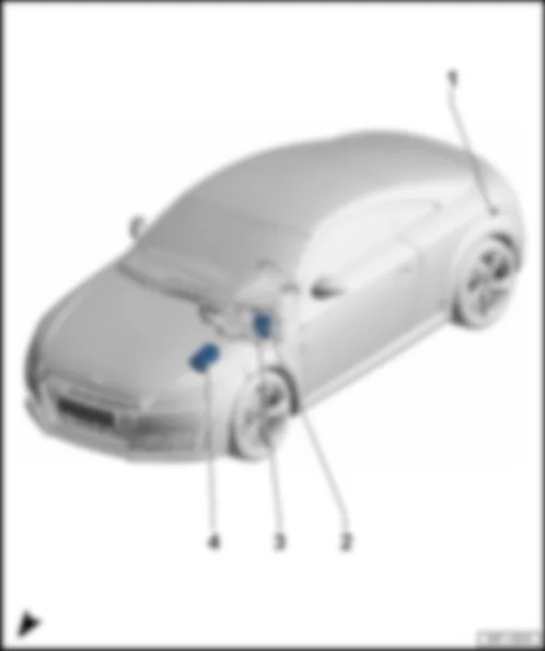
| Fitting location of main fuse carrier on the battery -A- |
| A - | Main fuse carrier on battery -A- |
| 1 - | Fuse 3 -S133- , 110 A |
| q | to fuse holder C -SC- |
| 2 - | Fuse 2 -S132- , 110 A |
| q | to fuse holder C -SC- |
| 3 - | Connection battery monitor control unit -J367- , 2-pin connector -T2a- , yellow |
| 4 - | Connection jump start connection -TV32- , 508 threaded connection (30) on electronics box, B1 |
| 5 - | Fuse 1 -S131- , 30 A |
| q | to Heated rear window relay -J9- , coupé |
| 5 - | Fuse 1 -S131- , 30 A |
| q | to fuse 2 on fuse holder D -SD2- , roadster |
| q | to fuse 1 on fuse holder F -SF1- , roadster |
| q | to fuse 2 on fuse holder F -SF2- , roadster |
|
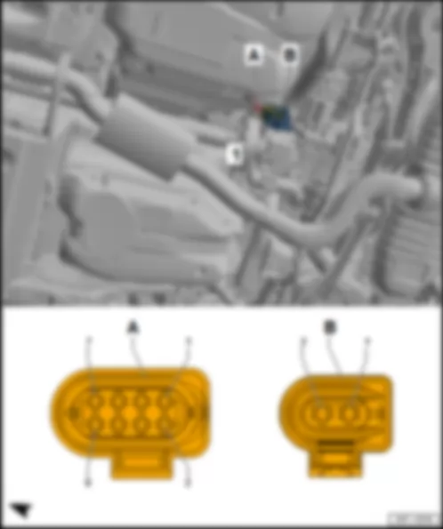
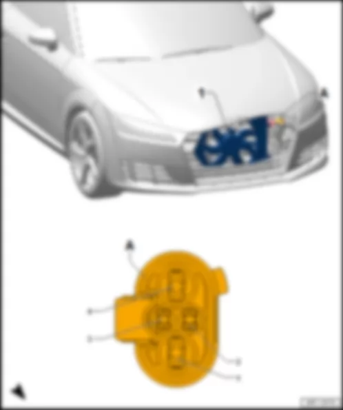
| Fitting location, jump start connection -TV32- /wiring junction -TV1- |
| 1 - | Jump start connection -TV32- , negative |
| 2 - | Jump start connection -TV32- , positive/wiring junction -TV1- |
| q | Positive connection, from main fuse carrier on battery -A- item 4 (A1), to 508 threaded connection (30) on electronics box, B1 |
| q | Positive connection to starter -B- , C1 |
|
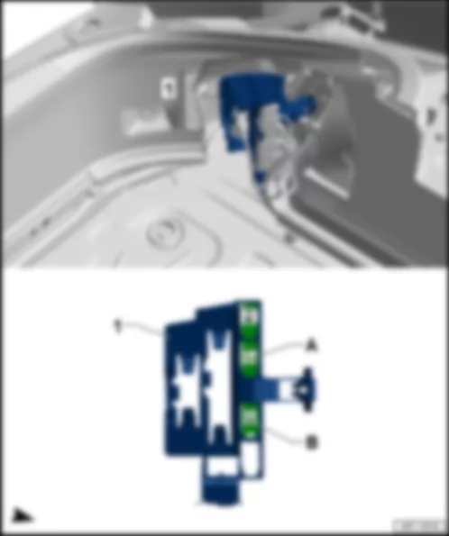
| Fitting location, relay and fuse carrier 4 -SR4- |
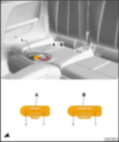
| 1 - | Relay and fuse carrier 4 -SR4- |
| A - | Fuse holder F -SF- |
| q | Fuse assignment |
| B - | Fuse holder D -SD- |
| q | Fuse assignment |
|
| Fuse assignment on fuse holder F -SF- |
| No. | Current Flow Diagram designation | Nominal value | Function/component | Terminal | ||
| 1 | - | Fuse 1 on fuse holder F -SF1- | 10 A | - | Convertible roof actuation control unit -J256- | 30 |
| 2 | - | Fuse 2 on fuse holder F -SF2- | 20 A | - | Heated rear window relay -J9- Heated rear window -Z1- | 30 |
|
| Fuse assignment on fuse holder D -SD- |
| No. | Current Flow Diagram designation | Nominal value | Function/component | Terminal | ||
| 1 | - | not assigned | - | |||
| 2 | - | Fuse 2 on fuse holder D -SD2- | 40 A | - | Convertible roof actuation control unit -J256- Convertible roof actuation motor -V82- Convertible roof actuation motor 2 -V576- | 30 |
|
 Deutsch
 English
 English
 Español
 Français
 Nederlands
 Русский

