RADIO
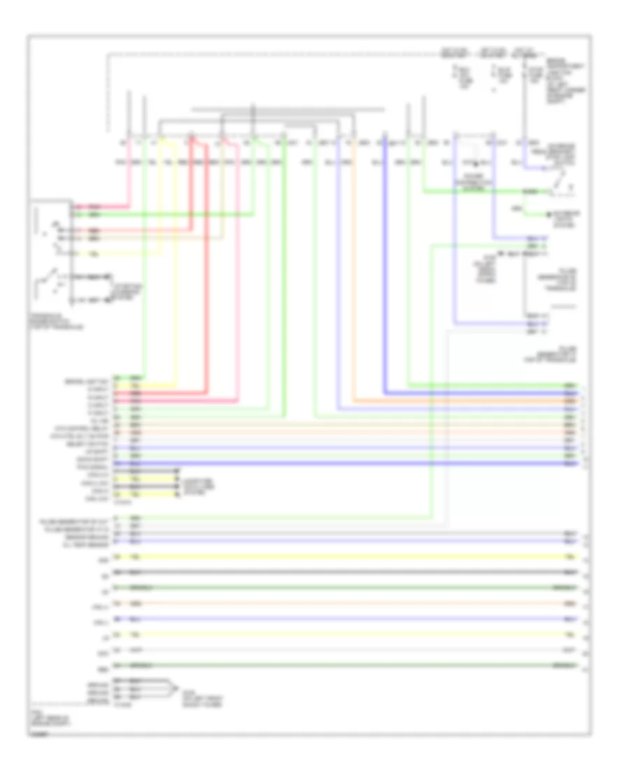
Radio Wiring Diagram, with Navigation & with AV Amplifier (1 of 2) for Hyundai Azera GLS 2011

List of elements for Radio Wiring Diagram, with Navigation & with AV Amplifier (1 of 2) for Hyundai Azera GLS 2011:
- (+)
- (-)
- (under center console)
- 12v sw1
- Acc/on in
- Alt l
- Aud in com
- Aud in l
- Aud in r
- Aud out com
- Aud out l
- Aud out r
- Audio
- Clock spring
- Eq sel
- F54-b
- F54-d
- Fbatt
- Fd11
- Fd12
- Ff21
- Fl (+)
- Fl (-)
- Fr (+)
- Fr (-)
- Gf01
- Gnd
- Hot at all times
- I/p junction box
- I/p-f
- Ill
- Ill (+)
- Ill (-)
- Interior lights system
- Lcd dim
- Led dim
- Left audio remocon switch
- Left front tweeter speaker
- M02-r
- M80-b
- M80-c1
- Memory power
- Mf81
- Mf91
- Mode
- Multifunction switch
- Mute
- Nca
- Pgnd
- Pnk
- Power
- R sw1
- R sw2
- Red
- Right front tweeter speaker
- Rl (+)
- Rl (-)
- Rr (+)
- Rr (-)
- Rse det
- Rse module (under front passenger's seat)
- Rse/ smart key fuse 10a
- Seek down
- Seek up
- Starting/charging system
- Steering wheel
- Sub woofer speaker
- Trim plate module
- Vol down
- Vol up
- W/ audio remocon
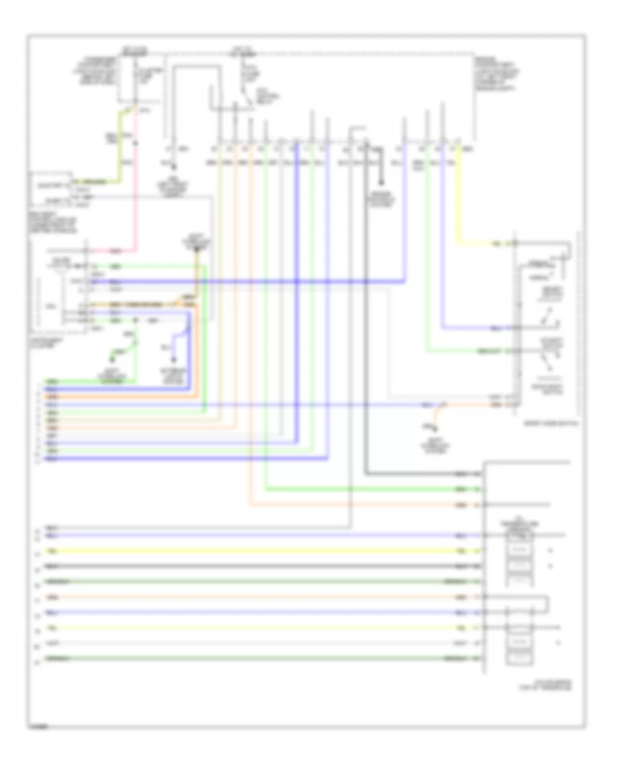
Radio Wiring Diagram, with Navigation & with AV Amplifier (2 of 2) for Hyundai Azera GLS 2011
List of elements for Radio Wiring Diagram, with Navigation & with AV Amplifier (2 of 2) for Hyundai Azera GLS 2011:
- (at left front corner of engine compt)
- (on brake pedal bracket) stop lamp switch
- 2nd
- Atm control relay
- Atm ctrl rly on pwr
- B/up fuse 10a
- Brake light sw
- C144-a
- C144-b
- Can 2 hi
- Can 2 low
- Can hi
- Can low
- Computer data lines system
- D input
- Dcc
- Down shift
- Ecu (ig1) fuse 10a
- Engine compartment junction block
- Exterior lights system
- G109 (on left front shock tower)
- Ground
- Hot at all times
- Hot in on or start
- Jc01
- Je01
- Je02
- Mil ind
- N input
- Oil temp sensor
- P input
- Pcm (left rear of engine compt)
- Pnk
- Power distribution system
- Pulse generator "a" (top of transaxle)
- Pulse generator "a" in
- Pulse generator "b" (top of transaxle)
- Pulse generator "b" out
- Pwm signal
- R input
- Red
- Select switch
- Sensor ground
- Starting/ charging
- Stop fuse 15a
- System
- Transaxle range switch (top of transaxle)
- Up shift
- Vfs (+)
- Vfs (-)
Radio Wiring Diagram, with Navigation & with JBL Amplifier (1 of 2) for Hyundai Azera GLS 2011
List of elements for Radio Wiring Diagram, with Navigation & with JBL Amplifier (1 of 2) for Hyundai Azera GLS 2011:
- Atm control relay
- Atm fuse 20a
- Atm solenoid (top of transaxle)
- Bcm (body control module) (under front of center console)
- Cluster fuse 10a
- Down shift switch
- Engine compartment junction block (at left front corner of engine compt)
- Engine controls system
- Exterior lights system
- G06 (left front of engine compt)
- Hot at all times
- Hot in on or start
- I/p-a
- Inhibit 'p'
- Instrument cluster
- Jc01
- Je01
- Je02
- M08-1
- M08-3
- M33-a
- M33-c
- Manual
- Mcu
- Mil ind
- Normal
- Oil temperature sensor
- On/start in
- Passenger compartment junction block (behind left side of dash)
- Pnk
- Pwm
- Select switch
- Shift interlock system
- Sport mode switch
- Up shift switch
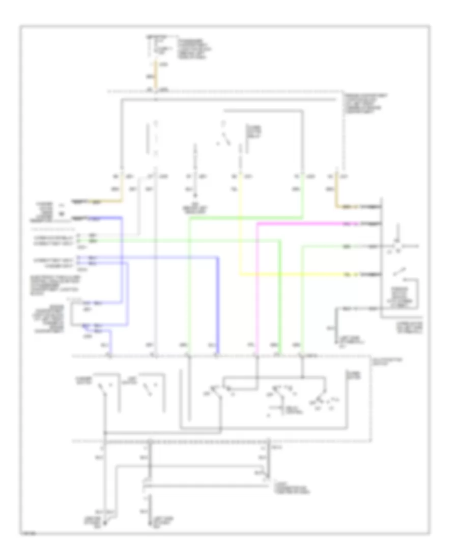
Radio Wiring Diagram, with Navigation & with JBL Amplifier (2 of 2) for Hyundai Azera GLS 2011
List of elements for Radio Wiring Diagram, with Navigation & with JBL Amplifier (2 of 2) for Hyundai Azera GLS 2011:
- (center of dash) g04
- (left side of dash) g03
- (left side of firewall) g11
- A12
- Delay control
- Electronic time & alarm control module (etacm) (in passenger compartment junction block)
- Engine compartment junction block (at left front corner of engine compartment)
- F12
- Fuse 11 15a
- G02 (behind left headlamp)
- Hot at on
- Int
- Intermittent input
- Jc01
- Je01
- Jm05
- Jm09
- Joint connector m08 (center of dash)
- M01-2
- M33-1
- M33-2
- Mist switch
- Multifunction switch
- Nca
- Off
- Parking switch (shown with wipers at rest)
- Passenger compartment junction block (behind left side of dash)
- Washer input
- Washer motor (near washer reservoir)
- Washer switch
- Wiper motor
- Wiper motor (on left side of firewall)
- Wiper motor relay
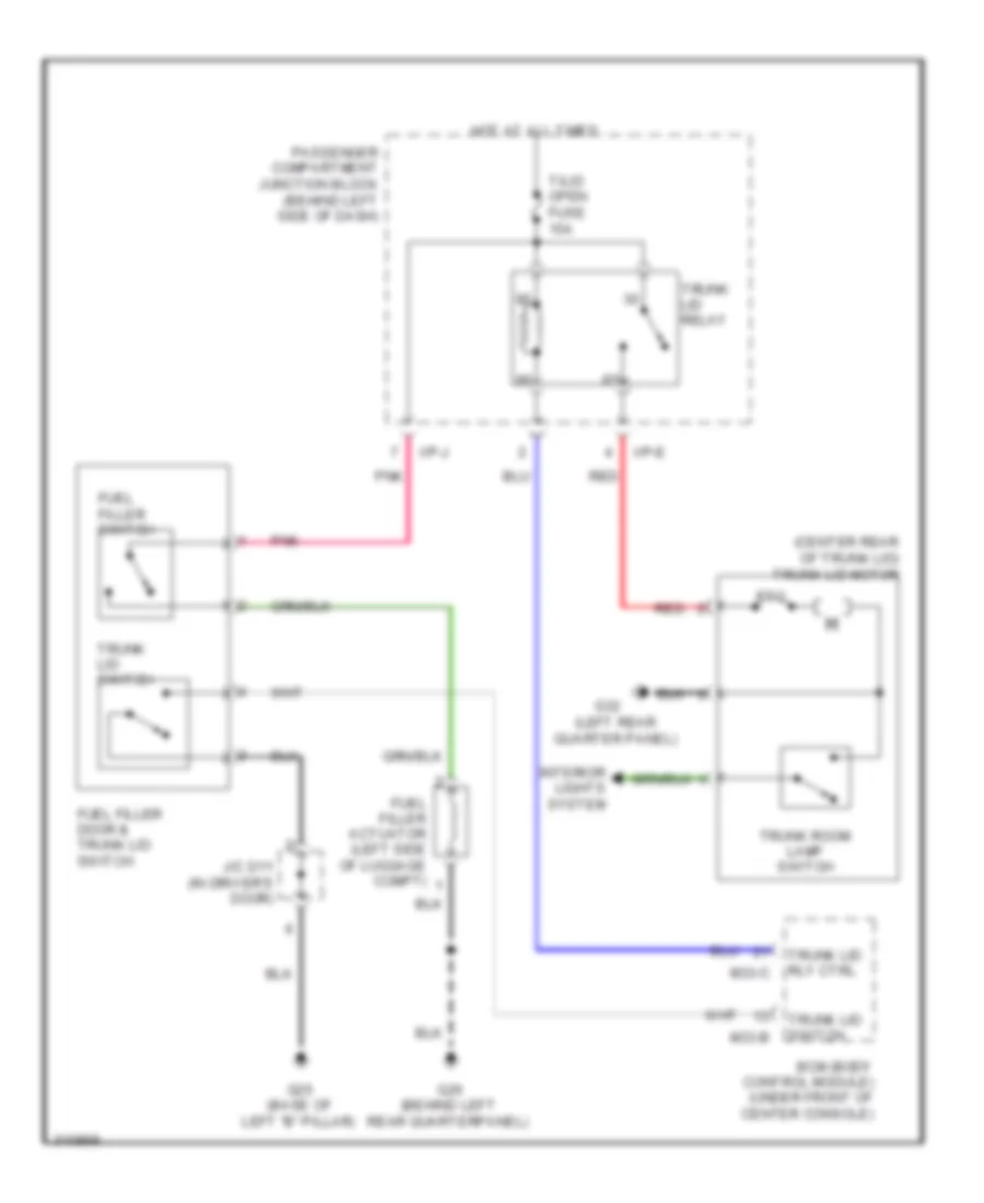
Radio Wiring Diagram, without Navigation & JBL Amplifier for Hyundai Azera GLS 2011
List of elements for Radio Wiring Diagram, without Navigation & JBL Amplifier for Hyundai Azera GLS 2011:
- (center rear of trunk lid) trunk lid motor
- (left rear quarter panel)
- Bcm (body control module) (under front of center console)
- Fuel filler actuator (left side of luggage compt)
- Fuel filler door & trunk lid switch
- Fuel filler switch
- G25 (base of left "b" pillar)
- G26 (behind left rear quarterpanel)
- G32
- Hot at all times
- I/p-e
- I/p-j
- Interior lights system
- J/c d11 (in driver's door)
- M33-b
- M33-c
- Passenger compartment junction block (behind left side of dash)
- Pnk
- Ptc
- Red
- T/lid open fuse 15a
- Trunk lid relay
- Trunk lid rly ctrl
- Trunk lid switch
- Trunk room lamp switch
Radio Wiring Diagram, without Navigation & with AV Amplifier (1 of 2) for Hyundai Azera GLS 2011
List of elements for Radio Wiring Diagram, without Navigation & with AV Amplifier (1 of 2) for Hyundai Azera GLS 2011:
- (left rear of engine compt)
- (right rear of transmission)
- Battery
- Bcm (center of dash)
- Body ground
- Clg-b
- Clg-zf
- Crank request
- Crank- ing sig (p/n)
- Ec21
- Ecm
- Elg-a
- Em21
- Escl sw fuse 10a
- Fob holder
- Fob in
- Ge03 (left front of engine compt)
- Hot at all times
- I/p junction box
- I/p-a
- Ign 2 fuse 40a
- Joint connector je71
- Key in sw
- Left e/r junction box (left side of engine compt)
- M51-a
- M51-b
- Pdm (left center of dash)
- Pnk
- Red
- Reserve (start-ems) m51-b
- Smart key control module (right side of dash)
- Ssb sw-1
- Ssb sw-2
- Ssb sw-2 m02-a
- Ssb sw-2 m14-a
- Start motor
- Start relay
- Start rly
- Start solenoid
- Start stop button switch
- Sub start relay
- Tcm
Radio Wiring Diagram, without Navigation & with AV Amplifier (2 of 2) for Hyundai Azera GLS 2011
List of elements for Radio Wiring Diagram, without Navigation & with AV Amplifier (2 of 2) for Hyundai Azera GLS 2011:
- (center of
- (left front of engine compt)
- (left rear of engine
- (left rear of engine compt)
- Acc
- B/ alarm ctrl
- B/alarm
- Battery
- Bcm
- Body ground
- Clg-b
- Clg-zf
- Compt)
- Crank request
- Crank- ing sig (p/n)
- Dash)
- Ec21
- Ecm
- Elg-a
- Em11
- Em21
- Ge03
- I/p junction box
- I/p-a
- Icm relay box (left side of dash)
- Ign 1 fuse 30a
- Ign 2 fuse 40a
- Ignition switch
- J/c je71
- Left e/r junction box (left side of engine compt)
- Lock
- M02-c
- M13-b
- Pnk
- Red
- Relay
- Start
- Start fuse 10a
- Start motor
- Start relay
- Start solenoid
- Sub start relay
- Tcm
- W/ immobilizer
- W/o immobilizer
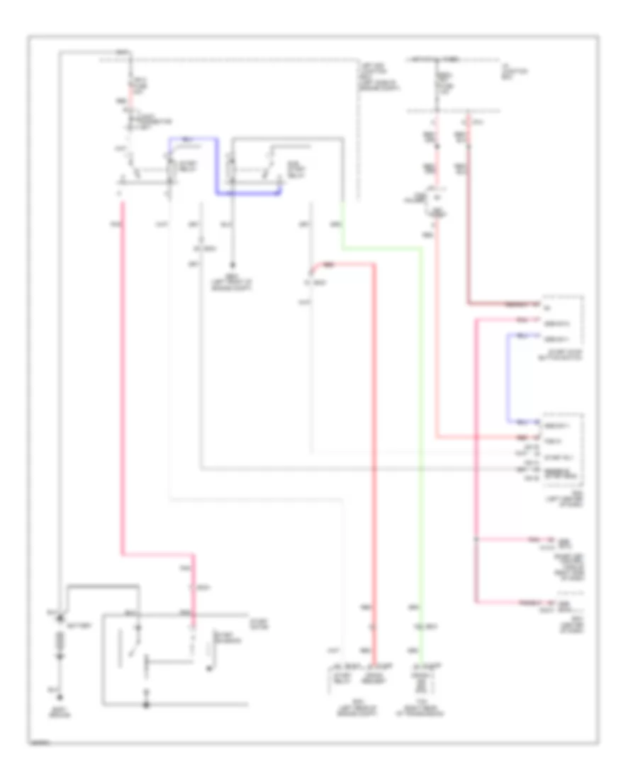
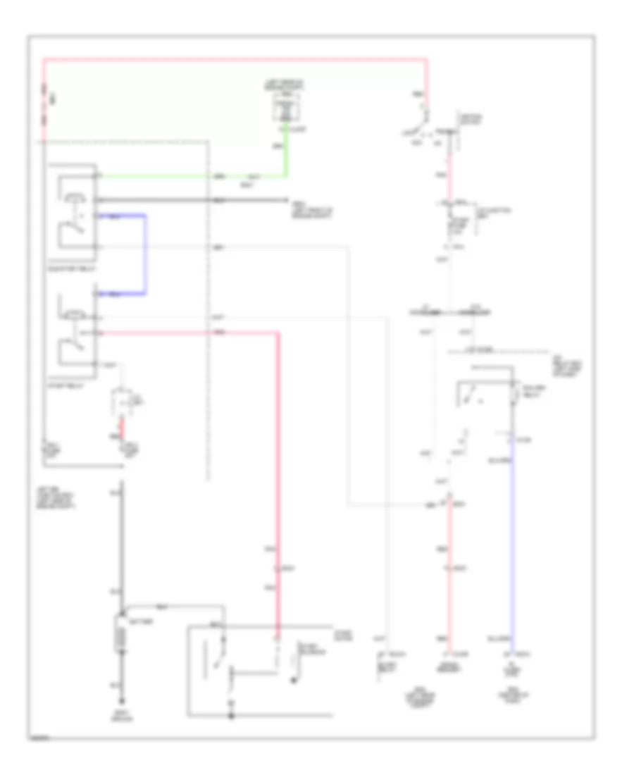
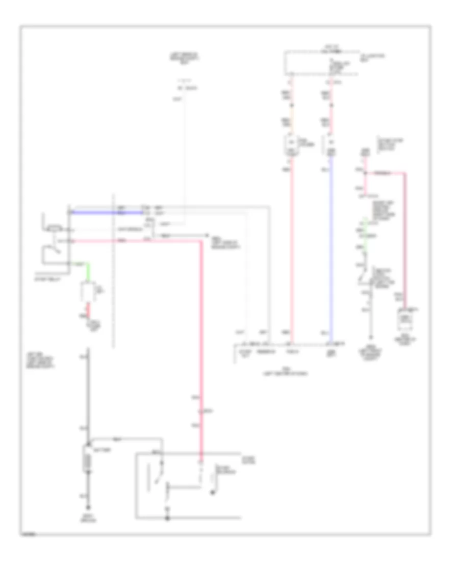
Radio Wiring Diagram, without Navigation & with JBL Amplifier (1 of 2) for Hyundai Azera GLS 2011
List of elements for Radio Wiring Diagram, without Navigation & with JBL Amplifier (1 of 2) for Hyundai Azera GLS 2011:
- (center of dash)
- (left center of dash)
- (left rear of engine compt)
- (left side of engine compt)
- 2.0l
- 3.8l
- All times
- Battery
- Bcm
- Body ground
- Ec21
- Ecm
- Elg-a
- Em21
- Em51
- Escl sw fuse 10a
- Fob holder
- Fob in
- Ge04
- Ge05 (left front of engine compt)
- Hot at
- I/p junction box
- I/p-a
- Ign 2 fuse 40a
- Ignition lock switch (left toe board)
- J/c je71
- Key in sw
- Left e/r junction box (left side of engine compt)
- M02-a
- M14-a
- M51-a
- M51-b
- Nca
- Pdm
- Pnk
- Pnk/
- Red
- Red/
- Reserve
- Rly
- Smart key control module (right side of dash)
- Ssb sw-1
- Ssb sw-2
- Start
- Start motor
- Start relay
- Start solenoid
- Start stop button switch
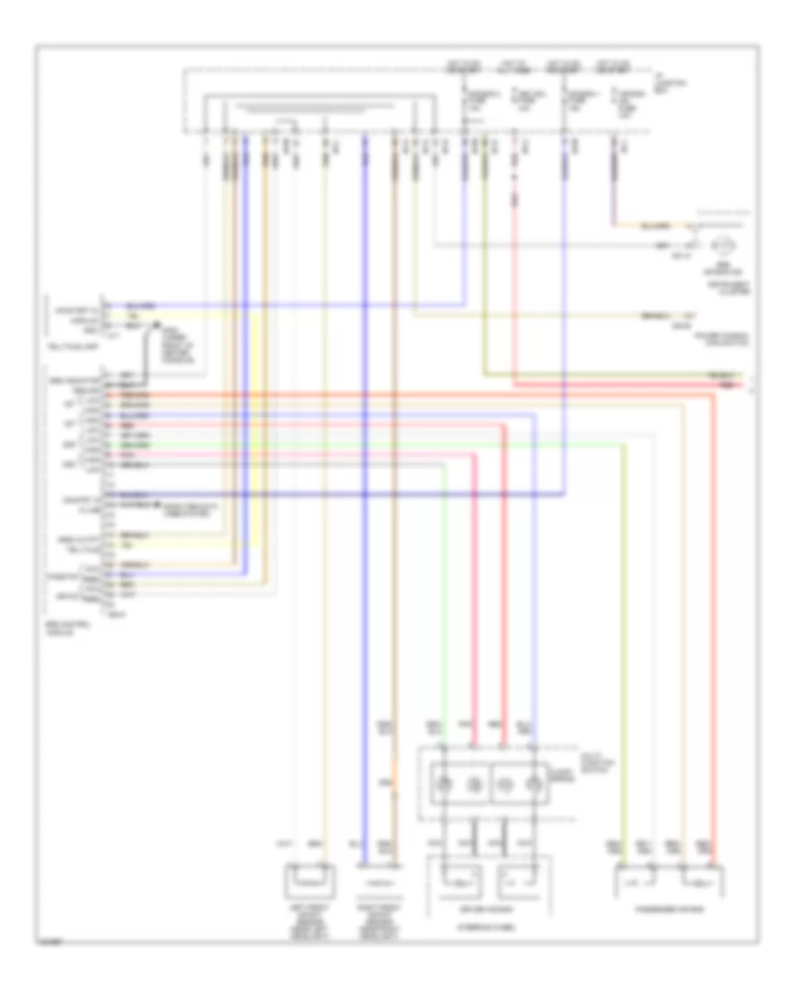
Radio Wiring Diagram, without Navigation & with JBL Amplifier (2 of 2) for Hyundai Azera GLS 2011
List of elements for Radio Wiring Diagram, without Navigation & with JBL Amplifier (2 of 2) for Hyundai Azera GLS 2011:
- 1st
- 2nd
- A05-a
- A17
- Air bag 1 fuse 15a
- Air bag 2 fuse 10a
- Air bag ind fuse 10a
- Clock spring
- Computer data lines system
- Crsh outpt
- D03-b
- Dr fis
- Driver air bag
- Feed
- Ga02 (under front of center console)
- Gnd
- Ground
- High
- Hot at all times
- Hot in on or start
- I/p junction box
- I/p-c
- I/p-d
- I/p-g
- I/p-h
- I/p-l
- I/p-m
- Instrument cluster
- K-line
- Key sol fuse 10a
- Left front impact sensor (near left headlight)
- Low
- M01-a
- Module
- Multi- function switch
- Nca
- On/start in
- On/strt in
- Pass fis
- Passenger air bag
- Pnk
- Power window main switch
- Red
- Right front impact sensor (near right headlight)
- Rtn
- Srs air bag ind
- Srs control module
- Srs indicator
- Steering wheel
- Telltale
- Telltale lamp