RADIO
Auto Pilot System Wiring Diagram for Mercedes-Benz E500 4Matic 2006

List of elements for Auto Pilot System Wiring Diagram for Mercedes-Benz E500 4Matic 2006:
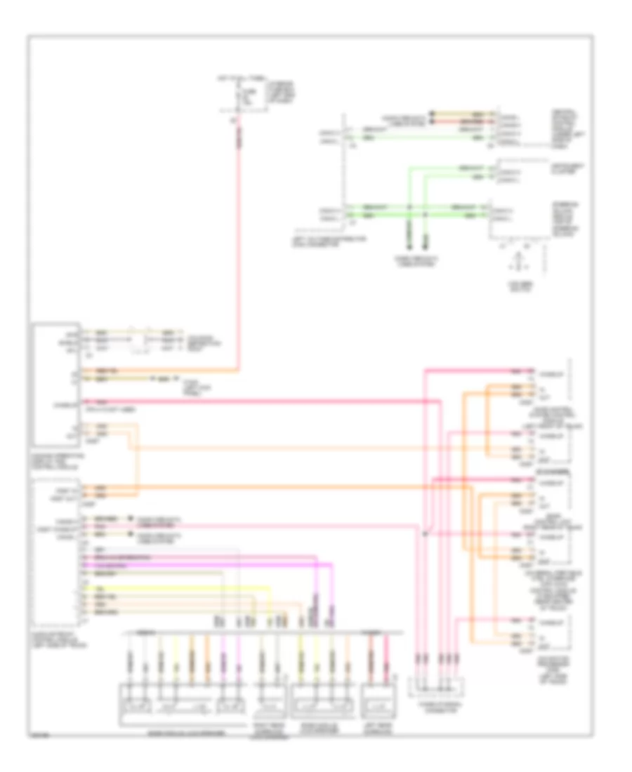
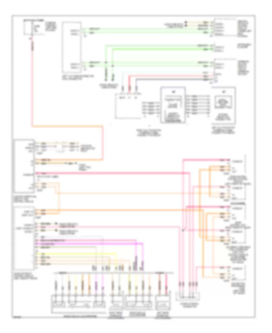
COMAND Actuation Wiring Diagram for Mercedes-Benz E500 4Matic 2006
List of elements for COMAND Actuation Wiring Diagram for Mercedes-Benz E500 4Matic 2006:
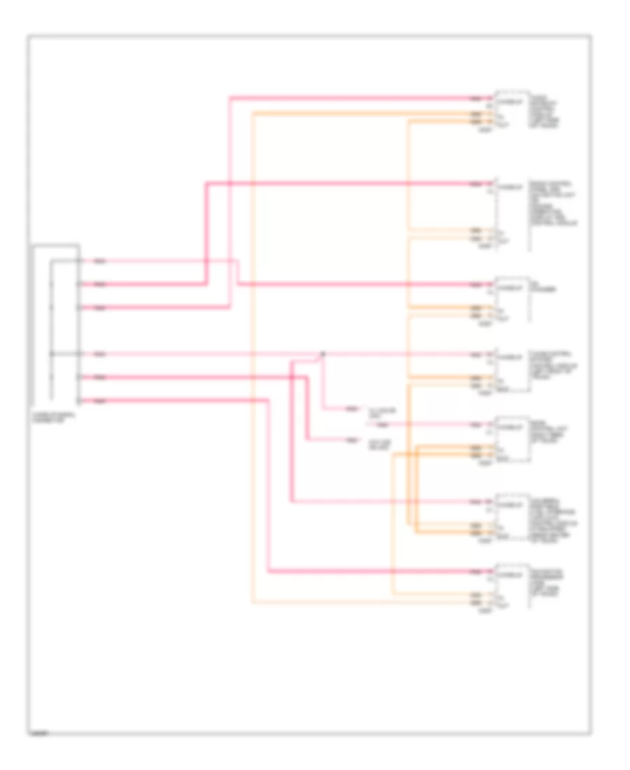
MOST Data Bus Wiring Diagram for Mercedes-Benz E500 4Matic 2006
List of elements for MOST Data Bus Wiring Diagram for Mercedes-Benz E500 4Matic 2006:
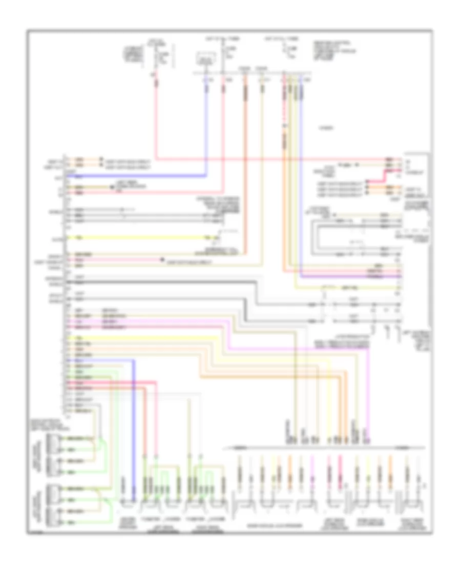
Radio Wiring Diagram for Mercedes-Benz E500 4Matic 2006
List of elements for Radio Wiring Diagram for Mercedes-Benz E500 4Matic 2006:
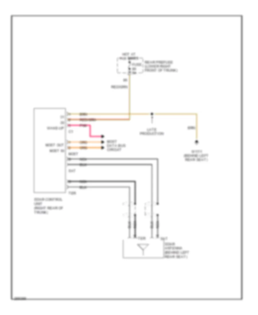
Satellite Radio Wiring Diagram for Mercedes-Benz E500 4Matic 2006
List of elements for Satellite Radio Wiring Diagram for Mercedes-Benz E500 4Matic 2006:
Voice Activation Wiring Diagram for Mercedes-Benz E500 4Matic 2006
List of elements for Voice Activation Wiring Diagram for Mercedes-Benz E500 4Matic 2006: