RADIO
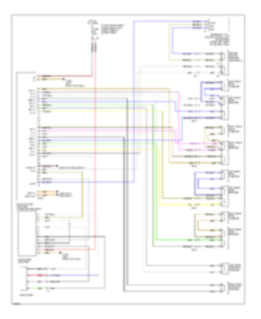
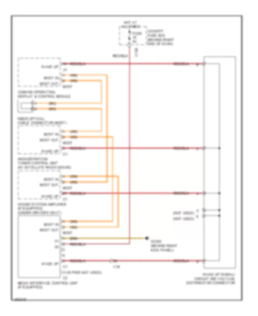
COMAND Actuation Wiring Diagram (1 of 2) for Mercedes-Benz GL350 2012

List of elements for COMAND Actuation Wiring Diagram (1 of 2) for Mercedes-Benz GL350 2012:
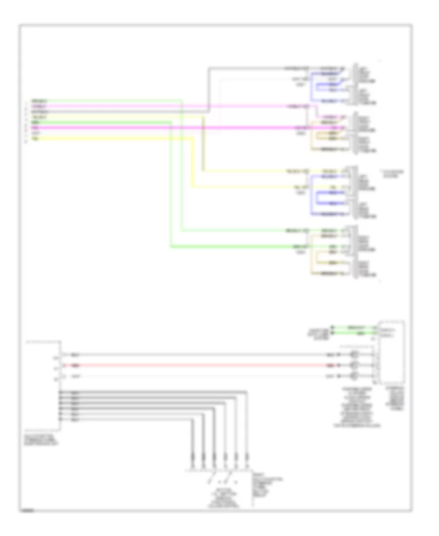
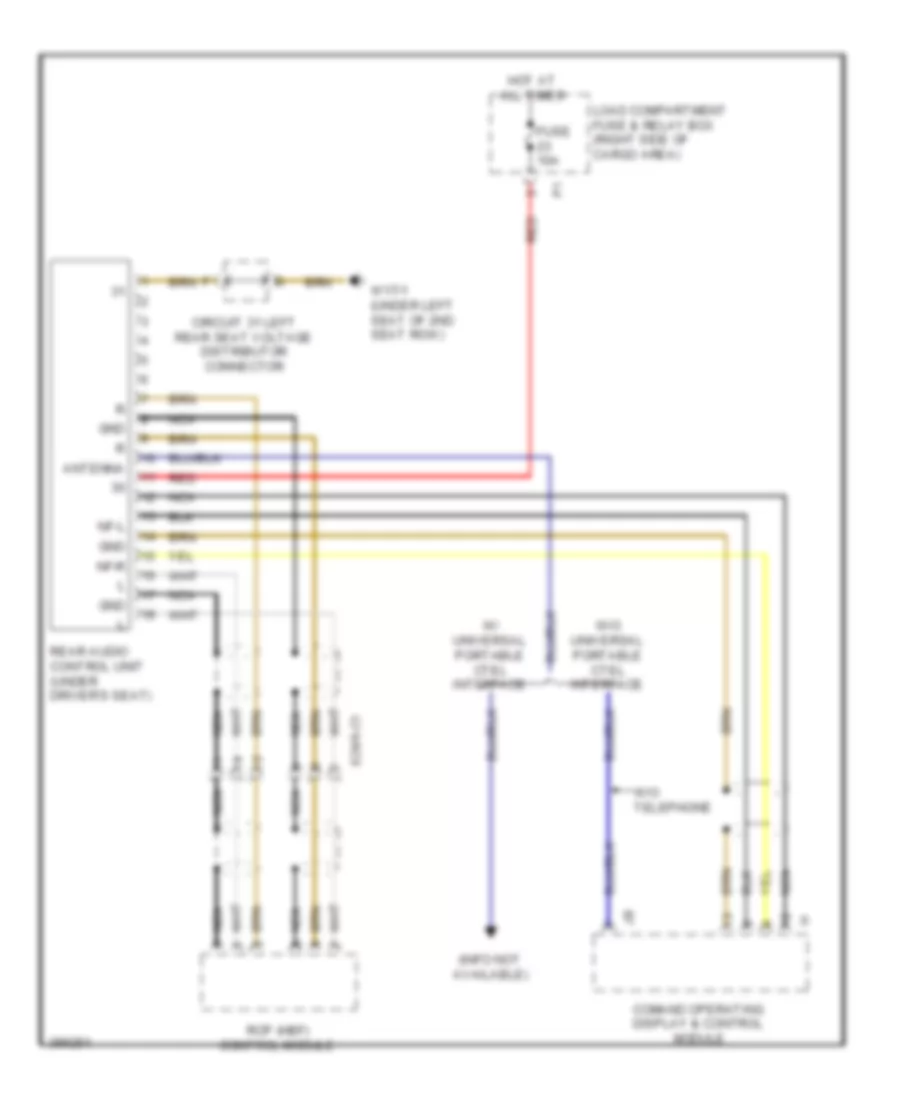
COMAND Actuation Wiring Diagram (2 of 2) for Mercedes-Benz GL350 2012
List of elements for COMAND Actuation Wiring Diagram (2 of 2) for Mercedes-Benz GL350 2012:
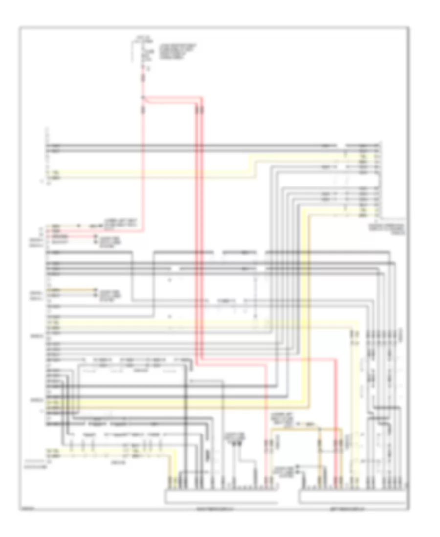
DVD Player Wiring Diagram for Mercedes-Benz GL350 2012
List of elements for DVD Player Wiring Diagram for Mercedes-Benz GL350 2012:
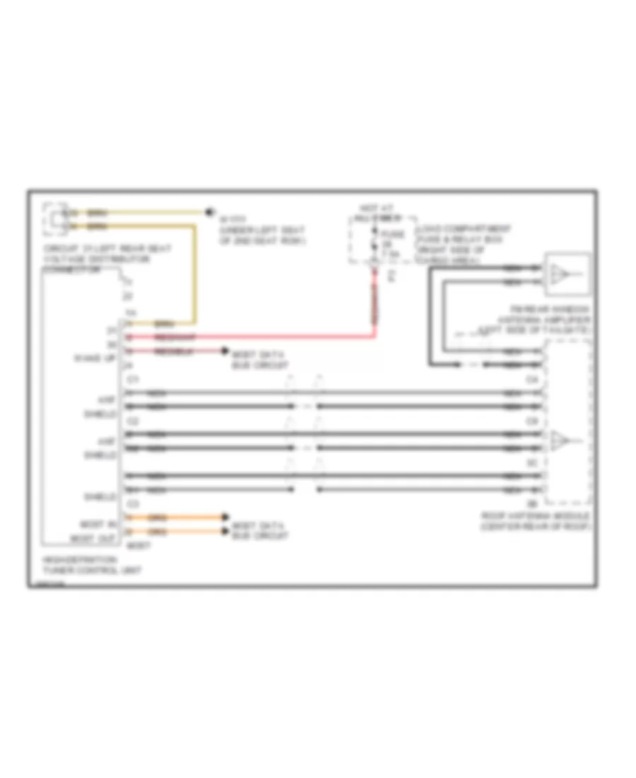
High Definition Tuner Wiring Diagram for Mercedes-Benz GL350 2012
List of elements for High Definition Tuner Wiring Diagram for Mercedes-Benz GL350 2012:
MOST Data Bus Wiring Diagram for Mercedes-Benz GL350 2012
List of elements for MOST Data Bus Wiring Diagram for Mercedes-Benz GL350 2012:
Rear Audio Wiring Diagram for Mercedes-Benz GL350 2012
List of elements for Rear Audio Wiring Diagram for Mercedes-Benz GL350 2012:
Sound Amplifier Wiring Diagram for Mercedes-Benz GL350 2012
List of elements for Sound Amplifier Wiring Diagram for Mercedes-Benz GL350 2012: