RADIO
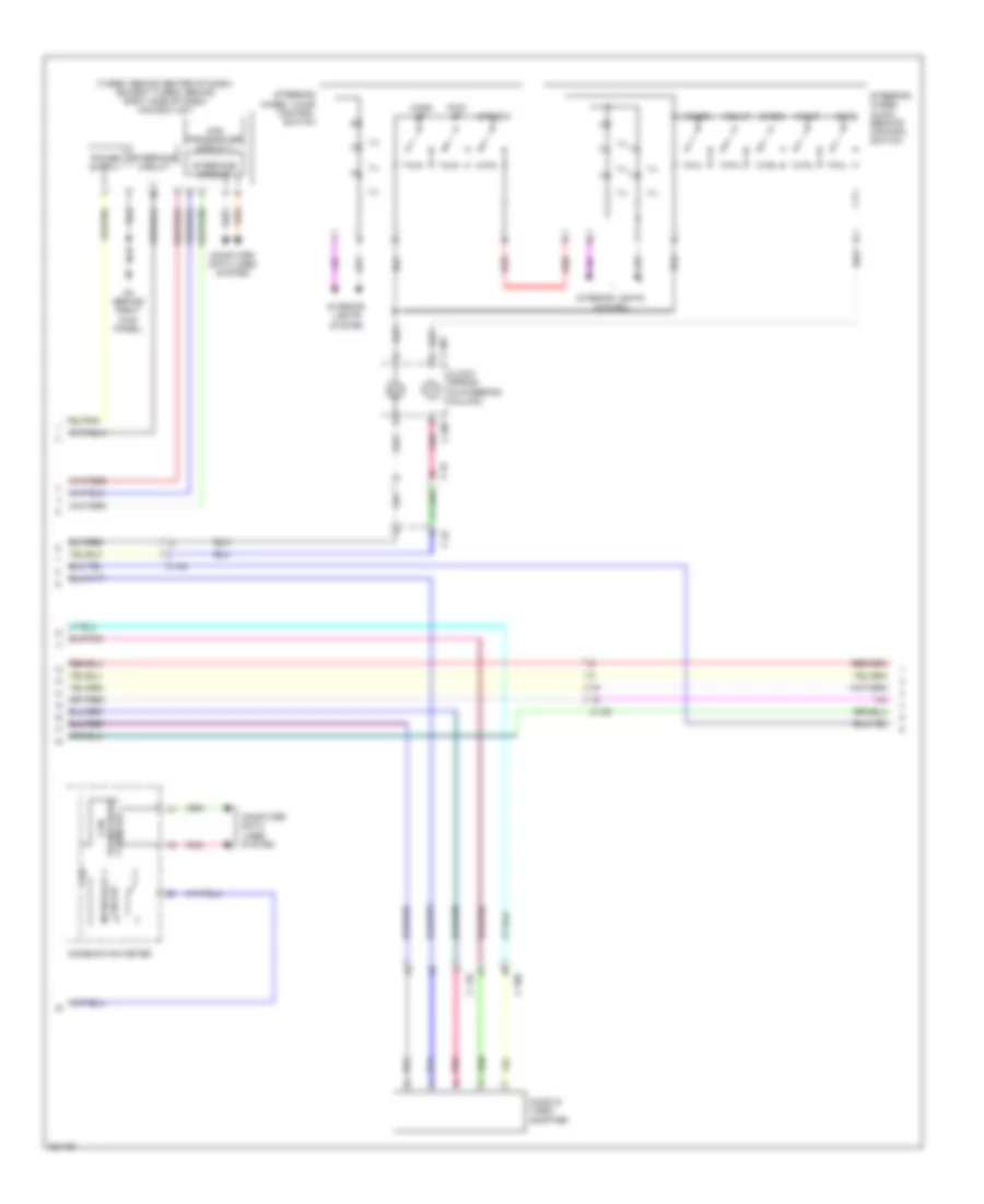
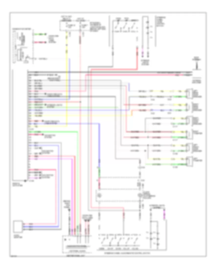
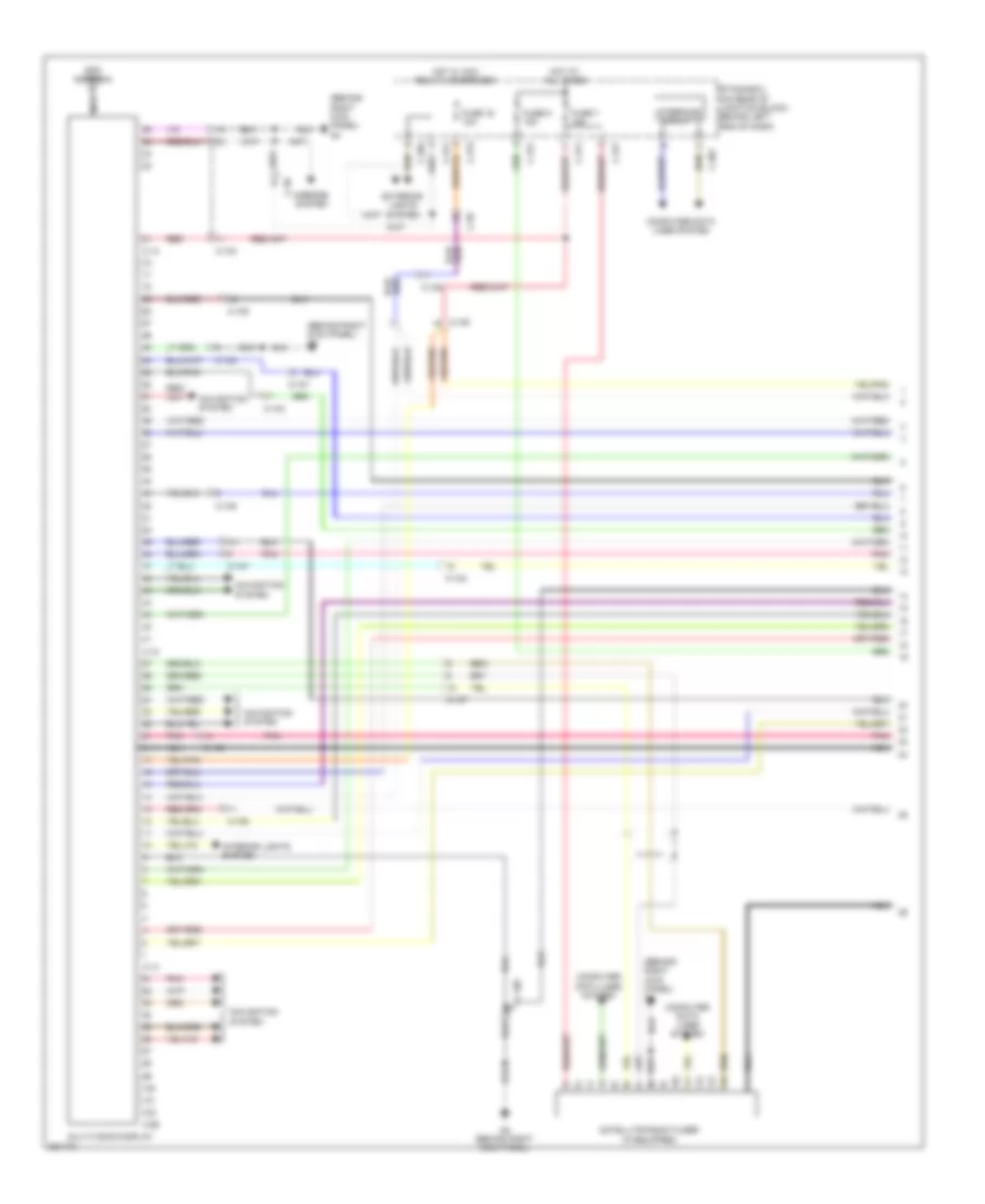
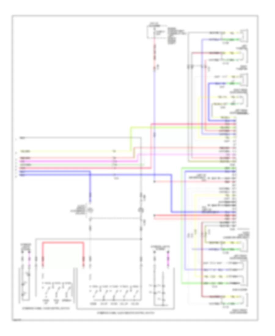
Radio Wiring Diagram, Evolution with Multi-Communication System (1 of 3) for Mitsubishi Lancer GT 2012

List of elements for Radio Wiring Diagram, Evolution with Multi-Communication System (1 of 3) for Mitsubishi Lancer GT 2012:
- (antenna feeder cable)
- (behind right kick panel) g4
- Antenna amplifier
- C-09
- C-10
- C-106
- C-108
- C-110
- C-12
- C-13
- C-304
- C-311
- C-315
- C-317
- C-42
- C108
- Cable) (gps antenna
- Computer data lines system
- Etacs-ecu (on rear of junction block, behind left end of dash)
- Exterior lights system
- Fuse 16 10a
- Fuse 7 15a
- G4 (behind right kick panel)
- Gps antenna
- Hot at all times
- Hot w/ acc relay 2 energized
- Interior lights system
- J/c c-43 (left kick panel)
- Mirrors system
- Multivision display
- Navigation system
- Nca
- Pnk
- Red
- Roof antenna
- Satellite radio tuner
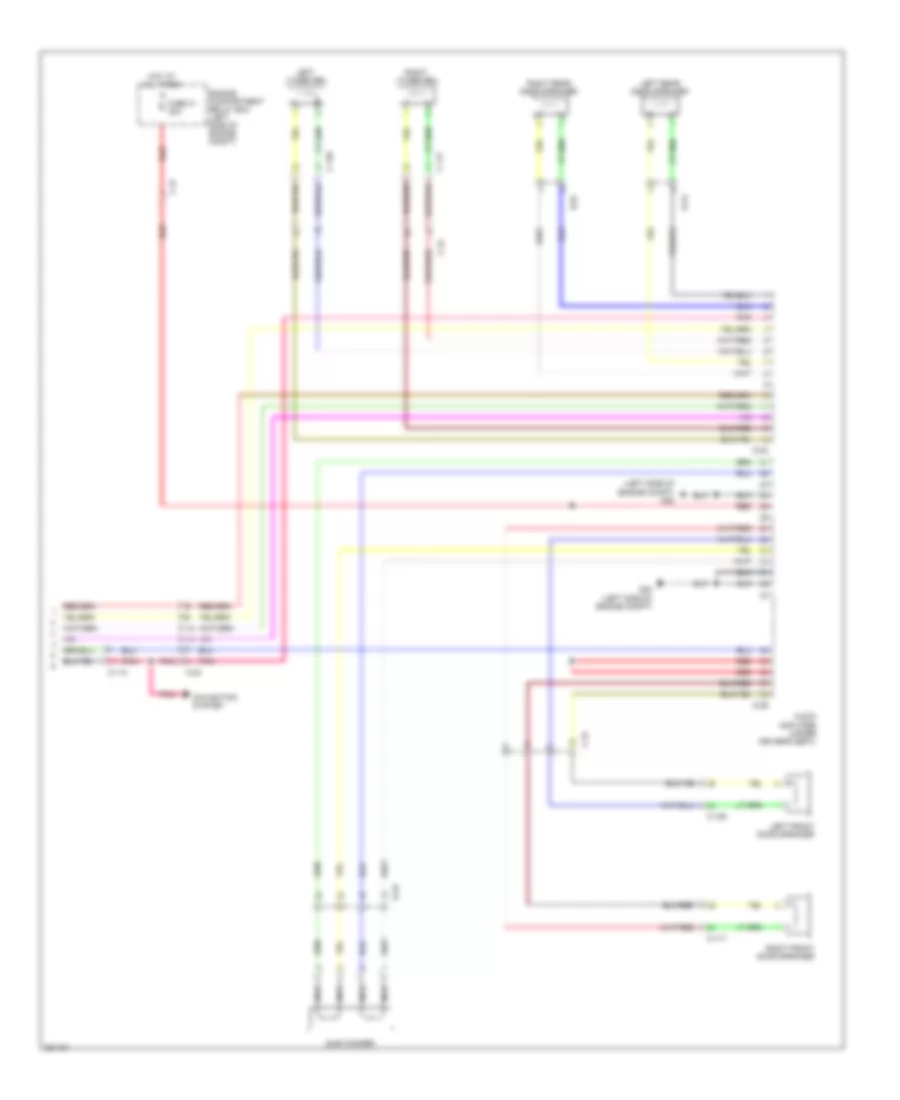
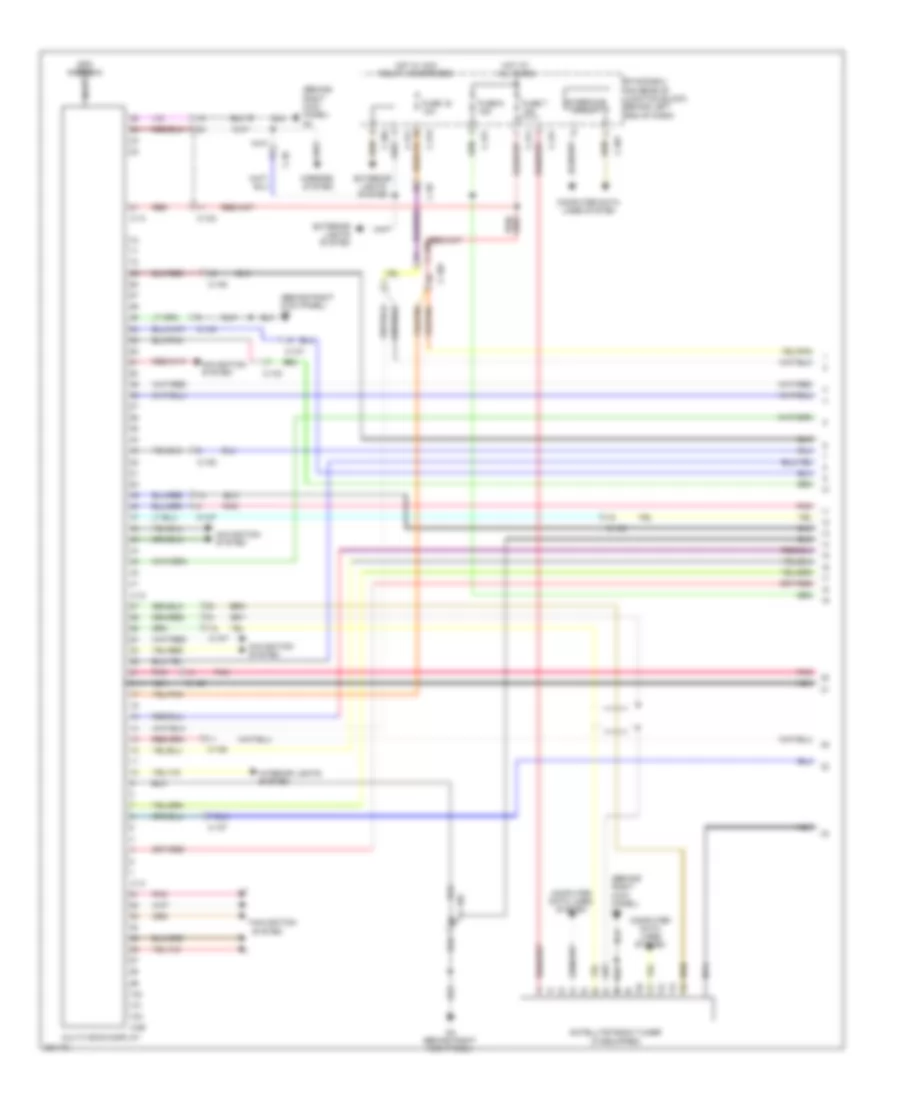
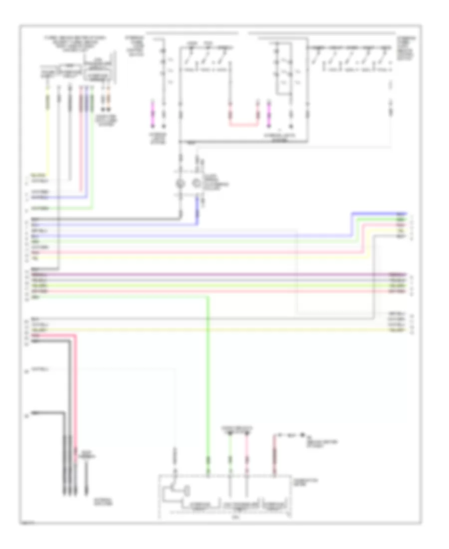
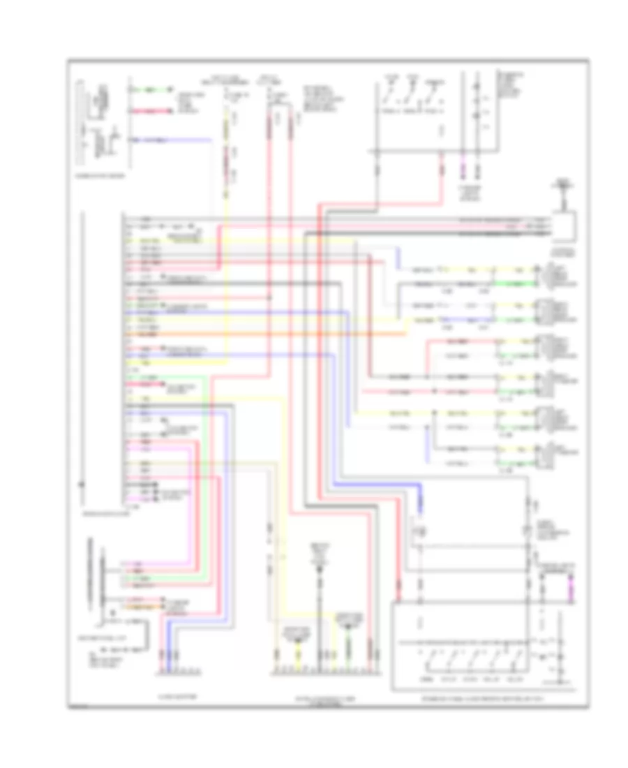
Radio Wiring Diagram, Evolution with Multi-Communication System (2 of 3) for Mitsubishi Lancer GT 2012
List of elements for Radio Wiring Diagram, Evolution with Multi-Communication System (2 of 3) for Mitsubishi Lancer GT 2012:
- (turbo: behind center of dash) (except turbo: behind right side of dash) can box unit
- Audio & video adapter
- C-106
- C-108
- C-110
- C-202
- C-205
- C-32
- Can transceiver circuit
- Ch dn
- Ch up
- Circuit interface
- Circuit transceiver can
- Clock spring (in steering column)
- Combination meter
- Computer data lines system
- Cpu
- G4 (behind right kick panel)
- Hang up
- Ill
- Interface circuit
- Interior lights system
- Mode
- Pick up
- Pnk
- Red
- Speech
- Steering wheel audio remote control switch
- Steering wheel voice control switch
- Vol dn
- Vol up
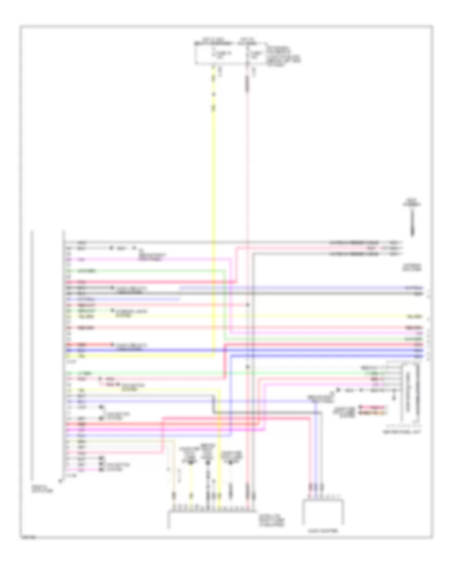
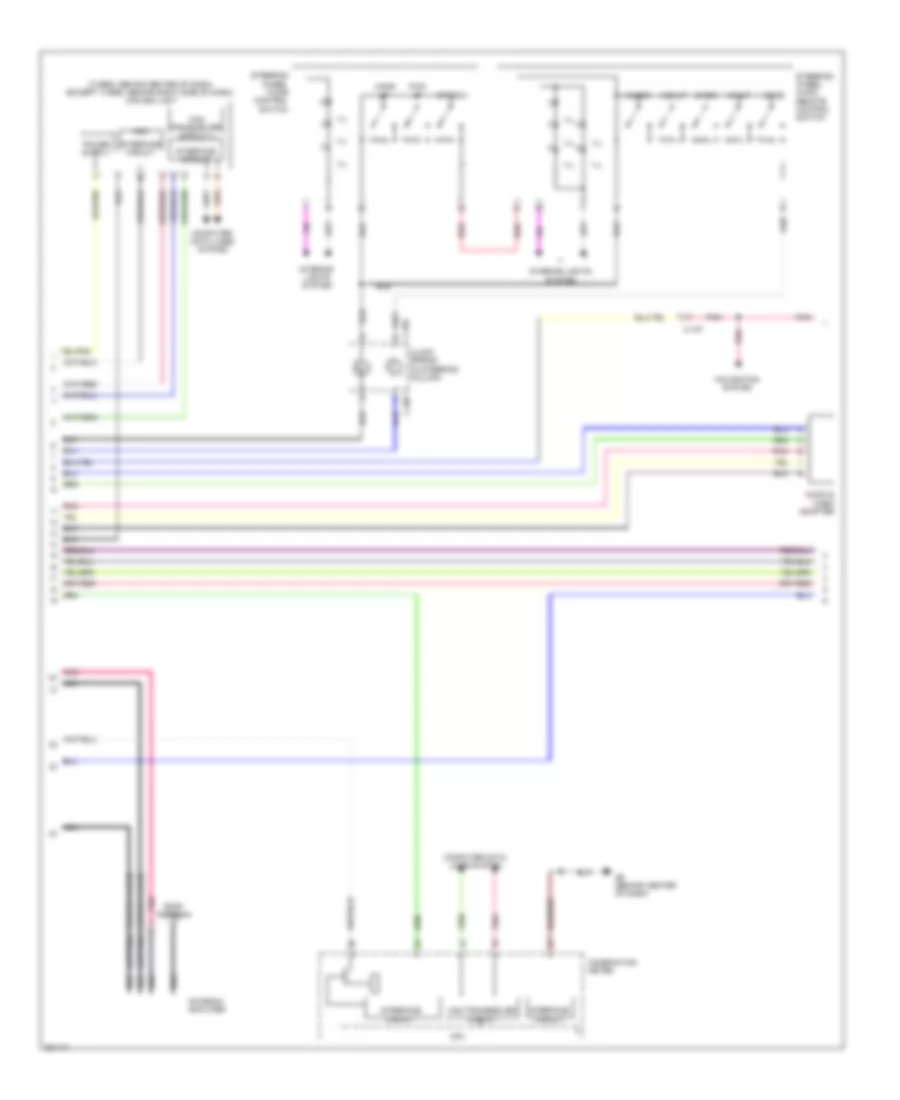
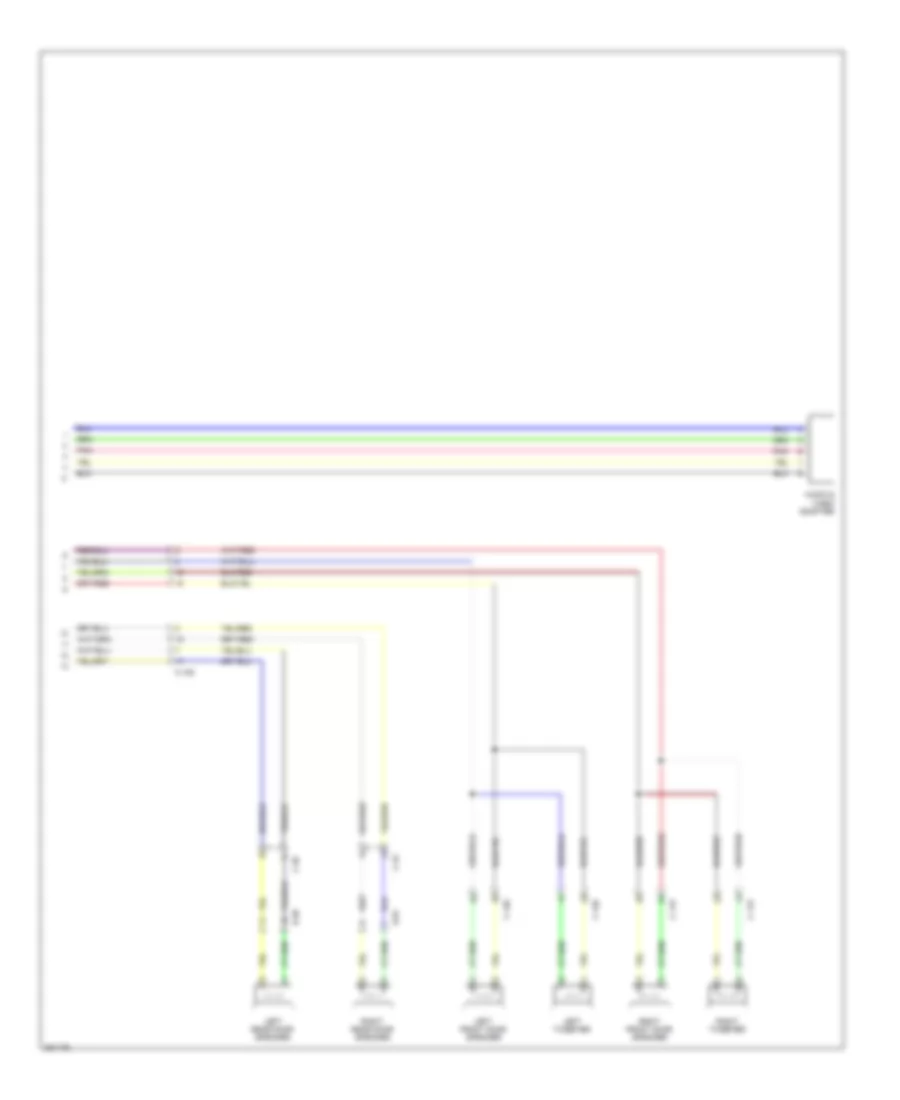
Radio Wiring Diagram, Evolution with Multi-Communication System (3 of 3) for Mitsubishi Lancer GT 2012
List of elements for Radio Wiring Diagram, Evolution with Multi-Communication System (3 of 3) for Mitsubishi Lancer GT 2012:
- (left side of engine compt) g20
- Audio amplifier (under driver's seat)
- C-110
- C-117
- C-129
- C-24
- C-47
- D-01
- D-16
- D-24
- D-29
- D-30
- Engine compartment relay box (left side of engine compt)
- Fuse 31 30a
- G20 (left side of engine compt)
- Hot at all times
- Left front door speaker
- Left rear door speaker
- Left tweeter
- Navigation system
- Nca
- Pnk
- Red
- Right front door speaker
- Right rear door speaker
- Right tweeter
- Sub woofer
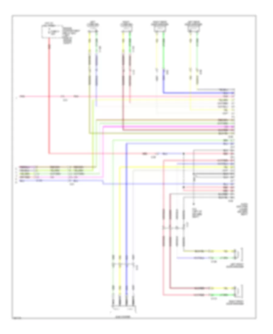
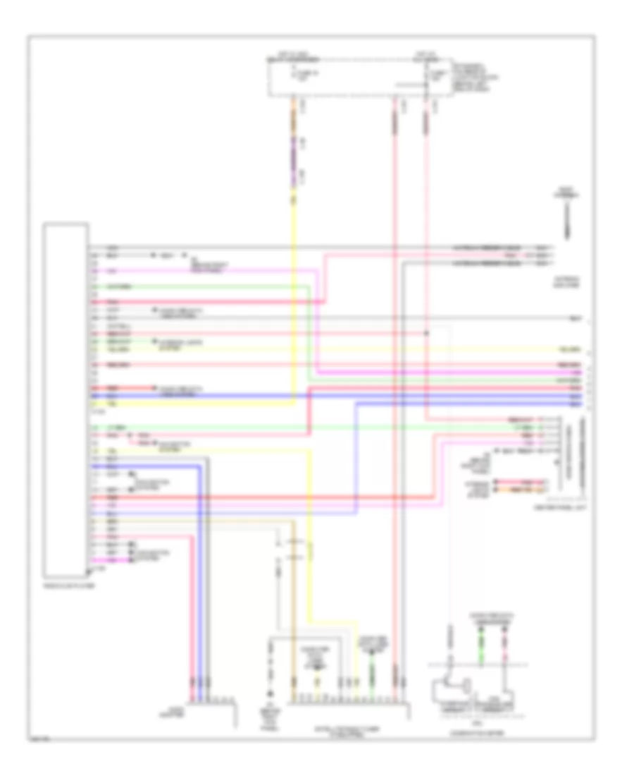
Radio Wiring Diagram, Evolution without Multi-Communication System with Amplifier (1 of 2) for Mitsubishi Lancer GT 2012
List of elements for Radio Wiring Diagram, Evolution without Multi-Communication System with Amplifier (1 of 2) for Mitsubishi Lancer GT 2012:
- (antenna feeder cable)
- (behind right kick panel) g4
- Antenna amplifier
- Audio adapter
- Audio switch panel
- C-107
- C-109
- C-315
- C-317
- Center panel unit
- Computer data lines system
- Etacs-ecu (on rear of junction block, behind left end of dash)
- Fuse 16 10a
- Fuse 7 15a
- G4 (behind right kick panel)
- Hot at all times
- Hot w/ acc relay 2 energized
- Interior lights system
- Lcd panel (audio, clock)
- Navigation system
- Nca
- Pnk
- Radio & cd player
- Red
- Roof antenna
- Satellite radio tuner (if equipped)
Radio Wiring Diagram, Evolution without Multi-Communication System with Amplifier (2 of 2) for Mitsubishi Lancer GT 2012
List of elements for Radio Wiring Diagram, Evolution without Multi-Communication System with Amplifier (2 of 2) for Mitsubishi Lancer GT 2012:
- Audio amplifier (under driver's seat)
- C-117
- C-129
- C-202
- C-205
- C-24
- C-32
- C-47
- Ch dn
- Ch up
- Circuit interface
- Circuit transceiver can
- Clock spring (in steering column)
- Combination meter
- Computer data lines system
- Cpu
- D-01
- D-16
- D-24
- D-29
- D-30
- Engine compartment relay box (left side of engine compt)
- Fuse 31 30a
- G20 (left side of engine compt)
- Hang up
- Hot at all times
- Ill
- Interior lights system
- Left front door speaker
- Left rear door speaker
- Left tweeter
- Mode
- Nca
- Pick up
- Pnk
- Red
- Right front door speaker
- Right rear door speaker
- Right tweeter
- Speech
- Steering wheel audio remote control switch
- Steering wheel voice control switch
- Sub woofer
- Vol dn
- Vol up
Radio Wiring Diagram, Evolution without Multi-Communication System without Amplifier for Mitsubishi Lancer GT 2012
List of elements for Radio Wiring Diagram, Evolution without Multi-Communication System without Amplifier for Mitsubishi Lancer GT 2012:
- (antenna feeder cable)
- (behind right kick panel) g4
- Antenna amplifier
- Audio adapter
- Audio switch panel
- C-107
- C-109
- C-117
- C-129
- C-202
- C-205
- C-23
- C-315
- C-317
- C-32
- C-42
- Can transceiver circuit
- Center panel unit
- Ch dn
- Ch up
- Clock spring (in steering column)
- Combination meter
- Computer data lines system
- Cpu
- D-01
- D-24
- Etacs-ecu (on rear of junction block, behind left end of dash)
- Fuse 16 10a
- Fuse 7 15a
- G4 (behind right kick panel)
- Hang up
- Hot at all times
- Hot w/ acc relay 2 energized
- Ill
- Interface circuit
- Interior lights system
- Lcd panel (audio)
- Left front door speaker
- Left rear door speaker
- Left tweeter
- Mode
- Navigation system
- Nca
- Pick up
- Pnk
- Radio & cd player
- Red
- Right front door speaker
- Right rear door speaker
- Right tweeter
- Roof antenna
- Speech
- Steering wheel audio remote control switch
- Steering wheel voice control switch
- Vol dn
- Vol up
Radio Wiring Diagram, Except Evolution with Multi-Communication System with Amplifier (1 of 3) for Mitsubishi Lancer GT 2012
List of elements for Radio Wiring Diagram, Except Evolution with Multi-Communication System with Amplifier (1 of 3) for Mitsubishi Lancer GT 2012:
- (behind right kick panel) g4
- C-103
- C-105
- C-107
- C-11
- C-12
- C-128
- C-13
- C-14
- C-301
- C-304
- C-311
- C-313
- C-317
- C-36
- C-39
- C-59
- Computer data lines system
- Etacs-ecu (on rear of junction block, behind left end of dash)
- Exterior lights system
- Fuse 16 10a
- Fuse 7 15a
- Fuse 9 15a
- G4 (behind right kick panel)
- Gps antenna
- Hot at all times
- Hot w/ acc relay 2 energized
- Interface circuit
- Interior lights system
- Mirrors system
- Multivision display
- Navigation system
- Nca
- Pnk
- Red
- Satellite radio tuner (if equipped)
Radio Wiring Diagram, Except Evolution with Multi-Communication System with Amplifier (2 of 3) for Mitsubishi Lancer GT 2012
List of elements for Radio Wiring Diagram, Except Evolution with Multi-Communication System with Amplifier (2 of 3) for Mitsubishi Lancer GT 2012:
- (antenna feeder cable)
- (turbo: behind center of dash) (except turbo: behind right side of dash) can box unit
- Acc
- Antenna amplifier
- Audio & video adapter
- C-107
- C-204
- C-205
- Can transceiver circuit
- Ch dn
- Ch up
- Clock spring (in steering column)
- Combination meter
- Computer data lines system
- Cpu
- G6 (behind center of dash)
- Hang up
- Ill
- Interface circuit
- Interior lights system
- Mode
- Navigation system
- Nca
- Pick up
- Pnk
- Red
- Roof antenna
- Speech
- Steering wheel audio remote control switch
- Steering wheel voice control switch
- Vol dn
- Vol up
Radio Wiring Diagram, Except Evolution with Multi-Communication System with Amplifier (3 of 3) for Mitsubishi Lancer GT 2012
List of elements for Radio Wiring Diagram, Except Evolution with Multi-Communication System with Amplifier (3 of 3) for Mitsubishi Lancer GT 2012:
- Audio amplifier (under driver's seat)
- C-105
- C-115
- C-126
- C-21
- C-39
- D-01
- D-15
- D-20
- D-25
- D-26
- Engine compartment relay box (left side of engine compt)
- Fuse 31 30a
- G12 (left of drivers seat)
- Hot at all times
- Left front door speaker
- Left rear door speaker
- Left tweeter
- Nca
- Pnk
- Red
- Right front door speaker
- Right rear door speaker
- Right tweeter
- Sub woofer
Radio Wiring Diagram, Except Evolution with Multi-Communication System without Amplifier (1 of 3) for Mitsubishi Lancer GT 2012
List of elements for Radio Wiring Diagram, Except Evolution with Multi-Communication System without Amplifier (1 of 3) for Mitsubishi Lancer GT 2012:
- (behind right kick panel) g4
- C-103
- C-105
- C-107
- C-11
- C-12
- C-128
- C-13
- C-14
- C-301
- C-304
- C-311
- C-313
- C-317
- C-36
- C-39
- C-59
- Computer data lines system
- Etacs-ecu (on rear of junction block, behind left end of dash)
- Exterior lights system
- Fuse 16 10a
- Fuse 7 15a
- Fuse 9 15a
- G4 (behind right kick panel)
- Gps antenna
- Hot at all times
- Hot w/ acc relay 2 energized
- Interface circuit
- Interior lights system
- Mirrors system
- Multivision display
- Navigation system
- Nca
- Pnk
- Red
- Satellite radio tuner (if equipped)
Radio Wiring Diagram, Except Evolution with Multi-Communication System without Amplifier (2 of 3) for Mitsubishi Lancer GT 2012
List of elements for Radio Wiring Diagram, Except Evolution with Multi-Communication System without Amplifier (2 of 3) for Mitsubishi Lancer GT 2012:
- (antenna feeder cable)
- (turbo: behind center of dash) (except turbo: behind right side of dash) can box unit
- Acc
- Antenna amplifier
- C-204
- C-205
- Can transceiver circuit
- Ch dn
- Ch up
- Clock spring (in steering column)
- Combination meter
- Computer data lines system
- Cpu
- G6 (behind center of dash)
- Hang up
- Ill
- Interface circuit
- Interior lights system
- Mode
- Nca
- Pick up
- Pnk
- Red
- Roof antenna
- Speech
- Steering wheel audio remote control switch
- Steering wheel voice control switch
- Vol dn
- Vol up
Radio Wiring Diagram, Except Evolution with Multi-Communication System without Amplifier (3 of 3) for Mitsubishi Lancer GT 2012
List of elements for Radio Wiring Diagram, Except Evolution with Multi-Communication System without Amplifier (3 of 3) for Mitsubishi Lancer GT 2012:
- Audio & video adapter
- C-105
- C-115
- C-126
- C-22
- C-36
- D-01
- D-20
- Left front door speaker
- Left rear door speaker
- Left tweeter
- Pnk
- Right front door speaker
- Right rear door speaker
- Right tweeter
Radio Wiring Diagram, Except Evolution without Multi-Communication System with Amplifier (1 of 2) for Mitsubishi Lancer GT 2012
List of elements for Radio Wiring Diagram, Except Evolution without Multi-Communication System with Amplifier (1 of 2) for Mitsubishi Lancer GT 2012:
- (antenna feeder cable)
- Antenna amplifier
- Audio adapter
- Audio switch panel
- Behind left end of dash)
- C-104
- C-106
- C-128
- C-311
- C-313
- C-317
- C-39
- Can transceiver circuit
- Center panel unit
- Combination meter
- Computer data lines system
- Cpu
- Etacs-ecu (on rear of junction block,
- Fuse 16 10a
- Fuse 7 15a
- G4 (behind right kick panel)
- Hot at all times
- Hot w/ acc relay 2 energized
- Interface circuit
- Interior lights system
- Lcd panel (audio, clock)
- Navigation system
- Nca
- Pnk
- Radio & cd player
- Red
- Roof antenna
- Satellite radio tuner (if equipped)
Radio Wiring Diagram, Except Evolution without Multi-Communication System with Amplifier (2 of 2) for Mitsubishi Lancer GT 2012
List of elements for Radio Wiring Diagram, Except Evolution without Multi-Communication System with Amplifier (2 of 2) for Mitsubishi Lancer GT 2012:
- (left of driver's seat) g12
- Audio amplifier (under driver's seat)
- C-115
- C-126
- C-204
- C-205
- C-21
- C-39
- Ch dn
- Ch up
- Clock spring (in steering column)
- D-01
- D-15
- D-20
- D-25
- D-26
- Engine compartment fuse/relay box (left side of engine compt)
- Fuse 31 30a
- G12 (left of driver's seat)
- Hang up
- Hot at all times
- Ill
- Interior lights system
- Left front door speaker
- Left rear door speaker
- Left tweeter
- Mode
- Nca
- Pick up
- Pnk
- Red
- Right front door speaker
- Right rear door speaker
- Right tweeter
- Speech
- Steering wheel audio remote control switch
- Steering wheel voice control switch
- Sub woofer
- Vol dn
- Vol up
Radio Wiring Diagram, Except Evolution without Multi-Communication System without Amplifier for Mitsubishi Lancer GT 2012
List of elements for Radio Wiring Diagram, Except Evolution without Multi-Communication System without Amplifier for Mitsubishi Lancer GT 2012:
- (antenna feeder cable)
- (behind right kick panel) g4
- Antenna amplifier
- Audio adapter
- Audio switch panel
- C-104
- C-106
- C-115
- C-126
- C-128
- C-204
- C-205
- C-22
- C-311
- C-313
- C-317
- C-36
- C-39
- Can
- Center panel unit
- Ch dn
- Ch up
- Clock spring (in steering column)
- Combination meter
- Computer data lines system
- Cpu
- D-01
- D-20
- Etacs-ecu (on rear of junction block, behind left end of dash)
- Fuse 16 10a
- Fuse 7 15a
- G4 (behind right kick panel)
- Hang up
- Hot at all times
- Hot w/ acc relay 2 energized
- Ill
- Interface circuit
- Interior lights system
- Lcd panel (audio, clock)
- Left front door speaker
- Left rear door speaker
- Left tweeter
- Mode
- Navigation system
- Nca
- Pick up
- Pnk
- Radio & cd player
- Red
- Right front door speaker
- Right rear door speaker
- Right tweeter
- Roof antenna
- Satellite radio tuner (if equipped)
- Speech
- Steering wheel audio remote control switch
- Steering wheel voice control switch
- Transceiver circuit
- Vol dn
- Vol up