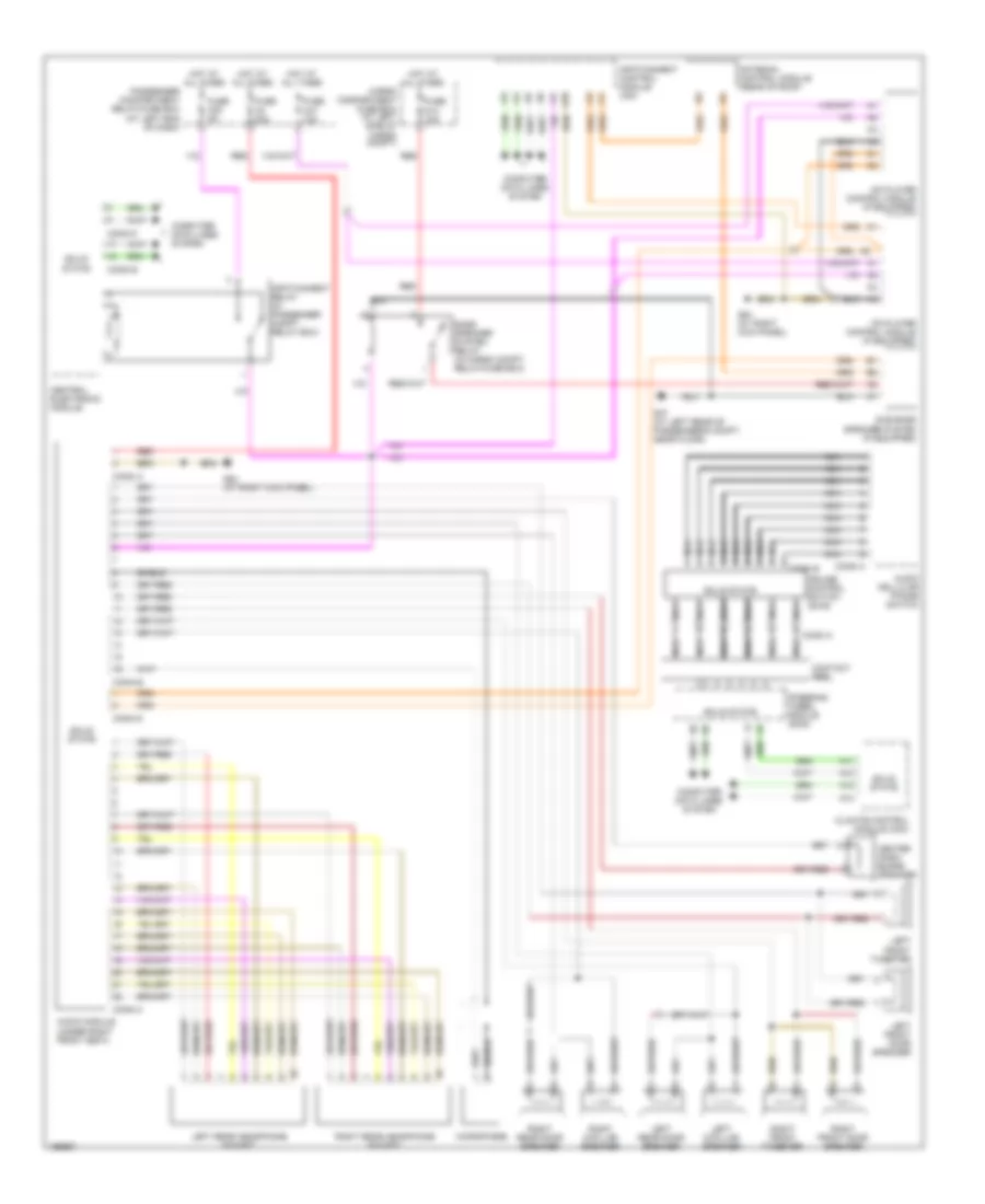
RADIO
Radio Wiring Diagram for Volvo XC90 2004
List of elements for Radio Wiring Diagram for Volvo XC90 2004:
- (at left end of dash)
- A10
- A11
- A12
- A13
- A14
- Antenna control module (rear of roof)
- Audio cellular phone switch
- Audio module (under right front seat)
- Bass speaker system relay (in cargo compt, relay/fuse box)
- Cargo compartment fuse box (at left side of cargo compt)
- Cd player control module (if equipped)
- Center dash- board speaker
- Central electronic module
- Climate control module (ccm)
- Computer data lines system
- Conn a
- Conn b
- Conn c
- Conn d
- Contact reel
- Cruise control switch (sws)
- Fuse c2 30a
- Fuse c20 5a
- Fuse c37 10a
- Fuse d13 15a
- G47 (at left rear of passenger's compt, near floor)
- G84 (at right kick panel)
- Hot at all times
- Infotainment control module (icm)
- Infotainment relay (in passenger compt relay box)
- Left d-pillar speaker
- Left front door speaker
- Left front tweeter
- Left rear door speaker
- Left rear headphone socket
- Md player control module (if equipped)
- Microphone
- Nca
- Passenger compartment relay/fuse box
- Red
- Right d-pillar speaker
- Right front door speaker
- Right front tweeter
- Right rear door speaker
- Right rear headphone socket
- Shield
- Solid state
- Steering wheel module (swm)
- Sub bass speaker system (if equipped)
 English