DEFOGGERS
Defoggers Wiring Diagram for Hyundai Elantra GLS 2010
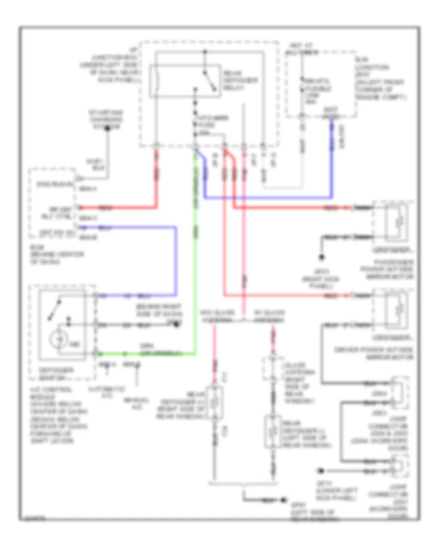
List of elements for Defoggers Wiring Diagram for Hyundai Elantra GLS 2010:
- (behind right side of dash) gm41
- (in left front corner of engine compt)
- (not used)
- A/c control module (wagon: below center of dash) (sedan: below center of dash) forward of shift lever)
- Automatic a/c
- Bcm (behind center of dash)
- Def sw in
- Defogger
- Defogger switch
- Driver power outside mirror motor
- E/r junction box
- E/r-frt
- Eng run in
- F11
- F24
- Gf11 (lower left kick panel)
- Gf21 (right kick panel)
- Gf81 (left side of rear window)
- Glass antenna (right side of rear window)
- Hot at all times
- Htd mirr fuse 10a
- I/p junction box (under left side of dash, near kick panel)
- I/p-b
- I/p-f
- I/p-g
- Ind
- Jd03
- Jd04
- Joint connector jd01 (in driver's door)
- Joint connector jd04 & jd03 (jd04: in driver's door)
- M04-a
- M04-b
- M05-a
- M06-b
- Manual a/c
- Nca
- Passenger power outside mirror motor
- Pnk
- Rear defogger (+) (right side of rear window)
- Rear defogger (-) (left side of rear window)
- Rear defogger relay
- Red
- Rr def rly ctrl m04-c
- Rr htd fusible link 40a
- Starting/ charging system
- W/ glass antenna
- W/o glass antenna
 Čeština
 Dansk
Dansk Deutsch
 Ελληνικά
 English
 English
 Español
 Suomi
Suomi Français
 Français
 עברית
עברית Hrvatski
 Magyar
 Italiano
 日本語
日本語 한국어
한국어 Nederlands
 Polski
 Português
 Português
 Русский
 Slovenčina
 Slovenščina
 Svenska
 Türkçe
 中文 (中国)
 Română