SHIFT INTERLOCK
Ignition Lock Solenoid Wiring Diagram for Hummer H3 2007
 https://portal-diagnostov.com/license.html
Automotive Electricians Portal FZCO
Automotive Electricians Portal FZCO
https://portal-diagnostov.com/license.html
https://portal-diagnostov.com/license.html
Automotive Electricians Portal FZCO
Automotive Electricians Portal FZCO
List of elements for Ignition Lock Solenoid Wiring Diagram for Hummer H3 2007:
- Automatic transmission floor shift control (beneath center console)
- Body control module (bcm) (behind right front kick panel)
- G106 (on right inner front wheel well)
- Hot at all times
- Ignition lock cylinder control actuator (on upper right side of steering column)
- Park position switch (closed in park)
- Rap relay
- Rap/accy relay
- S143
- S205
- Underhood fuse block (above left front wheel well)
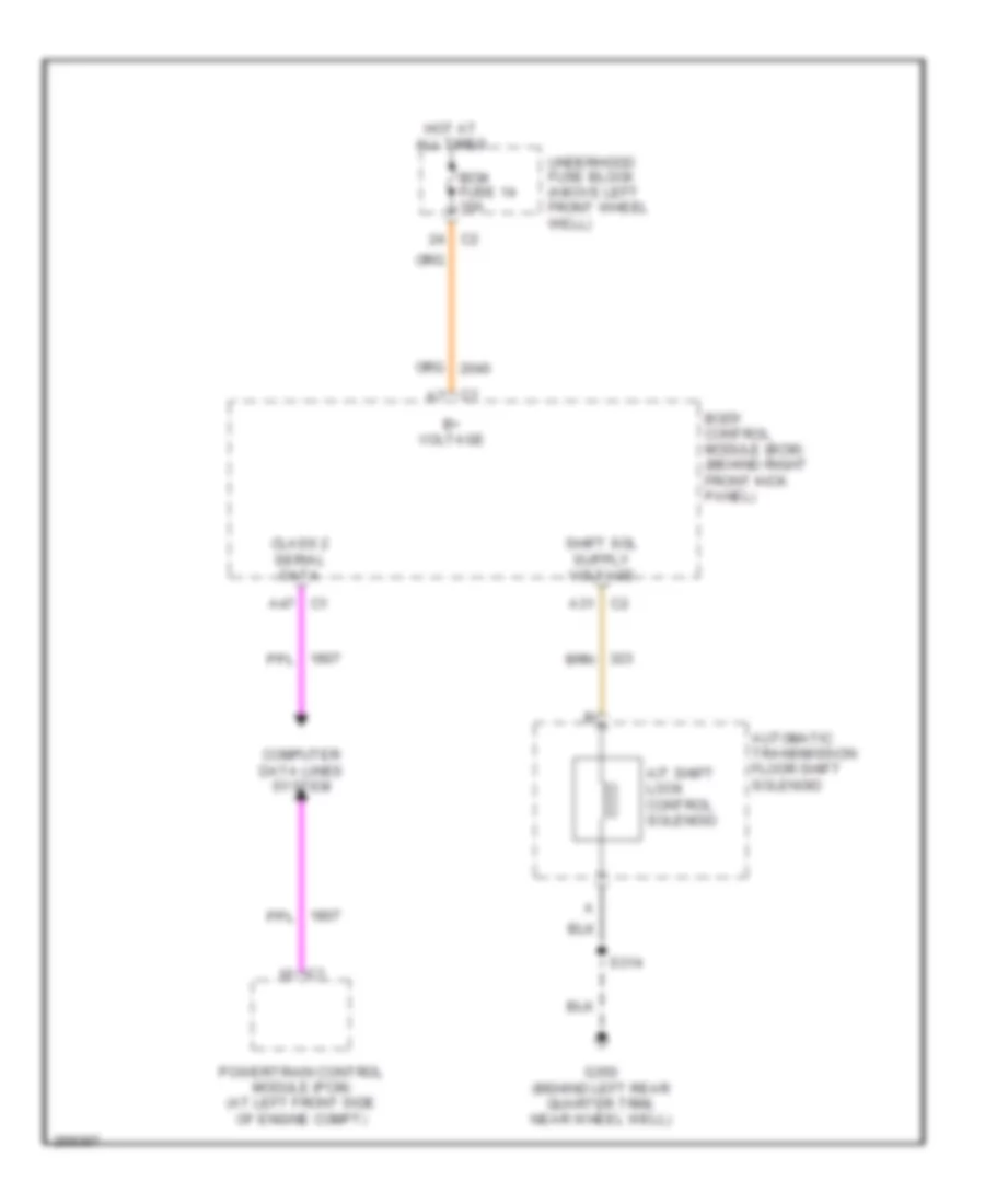
Shift Interlock Wiring Diagram for Hummer H3 2007
List of elements for Shift Interlock Wiring Diagram for Hummer H3 2007:
- A/t shift lock control solenoid
- A31 c2
- A47 c1
- Automatic transmission floor shift solenoid
- B+ voltage
- Bcm fuse 14 10a
- Body control module (bcm) (behind right front kick panel)
- C1 a7
- Class 2 serial data
- Computer data lines system
- G350 (behind left rear quarter trim, near wheel well)
- Hot at all times
- Powertrain control module (pcm) (at left front side of engine compt)
- S314
- Underhood fuse block (above left front wheel well)

 Čeština
 Dansk
Dansk Deutsch
 Ελληνικά
 English
 English
 Español
 Suomi
Suomi Français
 Français
 עברית
עברית Hrvatski
 Magyar
 Italiano
 日本語
日本語 한국어
한국어 Nederlands
 Polski
 Português
 Português
 Русский
 Slovenčina
 Slovenščina
 Svenska
 Türkçe
 中文 (中国)