AIR CONDITIONING
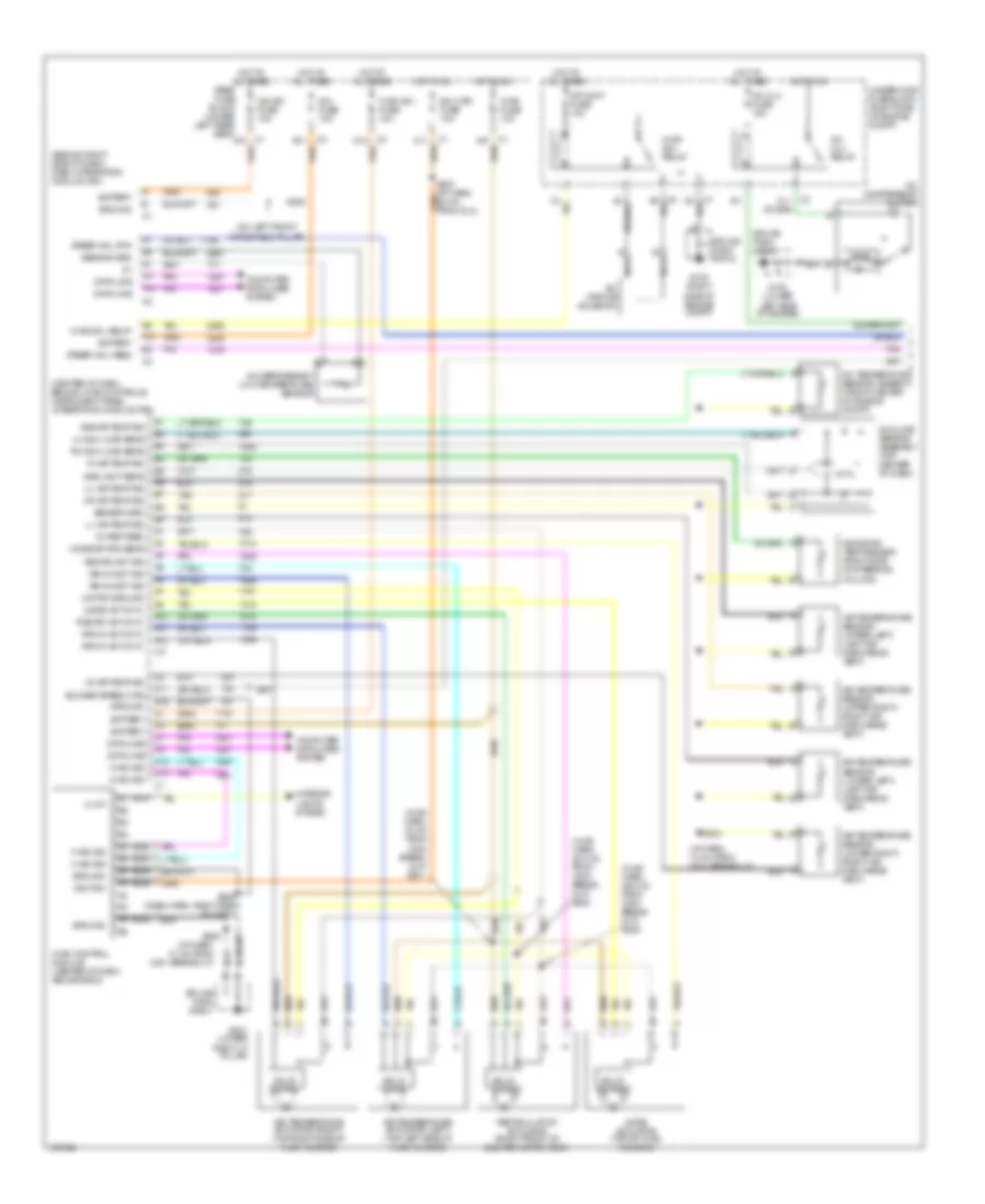
Automatic A/C Wiring Diagram (1 of 2) for Oldsmobile Aurora 2003
List of elements for Automatic A/C Wiring Diagram (1 of 2) for Oldsmobile Aurora 2003:
- (behind right side of dash) dash integration module (dim)
- (center of dash, behind hvac controls) instrument panel integration module (ipm)
- (hvac harn, 23.5 cm from c204 break- out) s222
- (hvac harn, 30 cm from c204 break- out)
- (hvac harn, 36.5 cm from c204 break- out) s220
- (i/p harn, 18 cm from c201 breakout)
- (i/p harn, 31 cm from c201 breakout)
- (on left front
- 5v ref feed
- A/c clu fuse 15a
- A/c clu relay
- A/c compressor clutch
- A/c orifice solenoid
- A/c refrigerant low temperature sensor
- A/c temperature sensor (ambient) (front center of engine compt)
- A10
- A11
- A12
- Air mix act cntl
- Air mix act sig
- Air temperature
- Air temperature actuator (left) (top left side of hvac housing)
- Air temperature actuator (right) (top right side of hvac housing)
- Air temperature sensor (lower right) (right air discharge vent)
- Air temperature sensor (upper left) (left air discharge vent)
- Air temperature sensor (upper right) (right air discharge vent)
- Amb air temp sig
- Amb light sens
- Battery
- Blower speed ctrl
- C1 a10
- C1 c11
- C12
- C13
- C3 d12
- C3 e11
- Computer data lines system
- Cr cont fuse 10a
- D11
- D16
- Data line
- Dim fuse 10a
- G100 (lower left side of engine)
- G103 (right side of engine compt)
- G200
- G201 (lower
- Ground
- Hot at all times
- Hot in on
- Hvac (b+) fuse 10a
- Hvac control module (center of dash, above radio)
- Hvac fuse 10a
- Hvac sig
- Hvac sol relay
- Ign 3 rr fuse 10a
- Ign sw fuse 15a
- Ignition
- Illum
- In air temp sig
- Inside air temp sensor (right side of steering column)
- Interior lights system
- Lh sun load sens
- Ll air temp sig
- Lr air temp sig
- Mode act cntl
- Mode actuator (top of hvac housing)
- Mode dr pos sens
- Motor ground
- Nca
- Rear fuse block (under left rear seat)
- Recirc act cntl
- Recirc act sig
- Recirculation actuator (right front of blower motor assy)
- Rh sun load sens
- Right "a" pillar)
- S204
- S205 (dash harn, right side of dash)
- S209
- S221
- Sensor (lower left) (left air discharge vent)
- Sensor grd
- Solid state
- Splice pack sp100
- Splice pack sp103
- Splice pack sp201
- Steer whl feed
- Steer whl rtn
- Sunload sensor assembly (top center of dash)
- Tan
- Ul air temp sig
- Underhood fuse block (right side of engine compt)
- Ur air temp sig
- Windshield pillar)
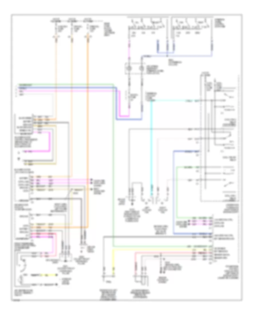
Automatic A/C Wiring Diagram (2 of 2) for Oldsmobile Aurora 2003
List of elements for Automatic A/C Wiring Diagram (2 of 2) for Oldsmobile Aurora 2003:
- (body harn, 14.5 cm from left power seat breakout)
- (engine harn, 6.5 cm from iac valve breakout)
- 5 v
- A/c enable
- A/c refrigerant pressure sensor (behind a/c compressor)
- Air temperature switch assembly (right)
- B10
- Battery
- Blower motor (on hvac housing)
- Blower motor control processor (behind dash, at right front of blower motor)
- Blwr ground
- Blwr speed
- Blwr volt
- Body computer system
- C1 a1
- C3 a7
- Computer data lines system
- Cool fan 1 fuse 30a
- Cool fan 1 relay (low speed)
- Cool fan 2 fuse 30a
- Cool fan 2 relay (high speed)
- Cool fan s/p relay
- D10
- Data
- Data line
- Driver door module (in driver door)
- Drv mdl fuse 10a
- E nca
- E10
- Ect sens sig
- Ect sense ground
- Engine controls system
- Engine coolant temperature (ect) sensor (rear of right cylinder head)
- F11
- Fan
- Front passenger door module (fpdm) (in passenger door)
- G nca
- G103 (right side of engine compt, in front of the underhood fuse block)
- G200 (on left front windshield pillar)
- G201 (on right front windshield pillar)
- Ground
- High spd fan ctrl
- Hot at all times
- Hvac blo fuse 30a
- Inflatable restraint steering wheel module coil
- Interior lights system
- Left cooling fan
- Low spd fan ctrl
- Nca
- Pass mdl fuse 10a
- Pnk
- Powertrain control module (pcm) (left side of engine compt, under air cleaner)
- Rear fuse block (under left rear seat)
- Right cooling fan
- S105 (engine harn, 9.5 cm from pcm c1 connector)
- S106
- S224 (in steering column)
- S302
- Select
- Sensor grd
- Sensor signal
- Speed ctrl
- Splice pack sp103
- Splice pack sp200
- Splice pack sp201
- Steering column fuse holder
- Steering wheel control switches
- Sw return
- Switch fuse 2a
- Temp
- Underhood fuse block (right side of engine compt)
- Vol
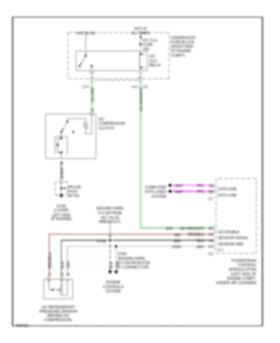
Compressor Wiring Diagram for Oldsmobile Aurora 2003
List of elements for Compressor Wiring Diagram for Oldsmobile Aurora 2003:
- (engine harn, 6.5 cm from iac valve breakout)
- 5 v
- A/c clu fuse 15a
- A/c clu relay
- A/c compressor clutch
- A/c enable
- A/c refrigerant pressure sensor (behind a/c compressor)
- Computer data lines system
- Data line
- Engine controls system
- G100 (lower
- Hot at all times
- Hot in on
- Left side of engine)
- Powertrain control module (pcm) (left side of engine compt, under air cleaner)
- S106
- Sensor grd
- Sensor signal
- Splice pack sp100
- Underhood fuse block (right side of engine compt)

 Čeština
 Dansk
Dansk Deutsch
 Ελληνικά
 English
 English
 Español
 Suomi
Suomi Français
 Français
 עברית
עברית Hrvatski
 Magyar
 Italiano
 日本語
日本語 한국어
한국어 Nederlands
 Polski
 Português
 Português
 Русский
 Slovenčina
 Slovenščina
 Svenska
 Türkçe
 中文 (中国)